1
F-9040-P
May, 2009
INSTRUCTIONS for
F-9040-
P
I. DESCRIPTION
The C-60 and C-60-S Machine Cutting Torches are
for use with any of the commonly used fuel gases such
as acetylene, natural gas, propane and many of the
proprietary gases. A minimum of 10 psi fuel gas pres-
sure is required for proper operation.
The basic difference between the C-60 and C-60-S
torches is in their overall length. The C-60 torch is ap-
proximately 6 feet long, while the C-60-S is approxi-
mately 2 1/2 feet long. The 1700-ACA-2 Power Cut-
ting Attachment is only for use with the C-60 torch.
II. INSTALLATION AND CONNECTION
A. INSTALLATION
1. A filter designed to screen out dirt and scale should
be installed upstream of the cutting oxygen regu-
lator which supplies the C-60 Torch. Use of a filter
reduces the possibility of accidental hose burn-
outs.
The 1-in. NPT Pipeline Filter Assembly (P/N
2116734) is recommended if the cutting oxygen
supply regulator is an Oxweld R-52 feeding a single
cutting station. In the case of multiple torch instal-
lations supplied by a single oxygen regulator, such
as an Oxweld R-83, filter (P/N 2116735) is recom-
mended.
2. A 1-in. quick opening full flow shutoff valve should
be installed in the cutting oxygen hose line at least
6 feet ahead of the torch and convenient to the op-
erating position.
3. For control of the preheat gases, “C” size oxygen
and acetylene needle valves should be inserted in
the preheat oxygen and fuel gas hose lines at least
6 feet ahead of the torch.
Standard commercial valves can be used after they
are cleaned and lubricated, to oxygen standards,
as described in maintenance procedures.
4. If using the 1700-ACA-2 Power Cutting Attachment
(10Y95) on the C-60, the ACV-4 Powder Pinch
Valve (16X36) should be installed in the powder
hose line about 5 feet ahead of the torch and con-
venient to the operator.
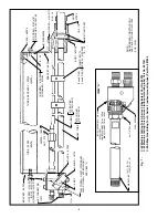
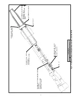
5. Connect the front clamp of powder cutting attach-
ment to front body of torch. Connect the two rear
clamps to the cutting-oxygen tube on the torch. (See
Fig. 2.)
These INSTRUCTIONS are for experienced operators. If you are not fully familiar with the principles of operation and safe prac-
tices for oxy-fuel gas equipment, we urge you to read our booklet “Precautions and Safe Practices for Welding, Cutting and
Heating”, Form 2035. Do NOT permit untrained persons to install, operate, or maintain this equipment. Do NOT attempt to install
or operate this equipment until you have read and fully understand these instructions. If you do not fully understand these
instructions, contact your supplier for further information.
The cutting torches covered by these instructions are listed by third parties only when using parts manufactured
by ESAB Welding & Cutting Products, to the specifications on file with third party listed, and when they are used
in the gas service for which they are designed and listed. The use of other parts that cause damage or failure to the equipment will
void the manufacturer’s warranty.
C-60 and C-60-S
MACHINE CUTTING TORCHES and
1700-ACA-1
POWDER CUTTING ATTACHMENT
Be sure this information reaches the operator.
You can get extra copies through your supplier.

