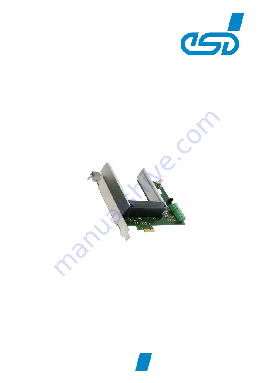
background image

AMC-PCIe-Carrier

PCI Express Adapter Board

for AMC Boards

Hardware Manual

to Product U.1003.01

AMC-PCIe-Carrier

Hardware Manual • Doc. No.: U.1003.21 / Rev. 1.1

Page 1 of 16

                                          esd electronic system design gmbh
             Vahrenwalder Str. 207 • 30165 Hannover • Germany
                                                                   http://www.esd.eu   
Phone: +49 (0) 511 3 72 98-0 • Fax: +49 (0) 511 3 72 98-68

Summary of Contents for AMC-PCIe-Carrier

Page 1: ...rds Hardware Manual to Product U 1003 01 AMC PCIe Carrier Hardware Manual Doc No U 1003 21 Rev 1 1 Page 1 of 16 esd electronic system design gmbh Vahrenwalder Str 207 30165 Hannover Germany http www e...

Page 2: ...rights to this documentation are reserved by esd Distribution to third parties and reproduction of this document in any form whole or in part are subject to esd s written approval 2013 esd electronic...

Page 3: ...below affect changes in the hardware as well as changes in the description of the facts only Revision Chapter Changes versus previous version Date 1 0 First version 2012 07 04 1 1 Title changed 2013...

Page 4: ...to electronic components To avoid this please perform the steps described on page 10 before you touch the AMC PCIe Carrier in order to discharge the static electricity from your body Qualified Persona...

Page 5: ...s 9 3 Hardware Installation 10 4 Technical Data 12 4 1 General Technical Data 12 4 2 MicroTCATM AMC Standards 12 4 3 PCI Express Interface 13 4 4 Current Measurement 13 4 5 Voltage Measurement 13 4 6...

Page 6: ...the board indicate the status of the power supply and of the Hot Swap controller For cooling of the inserted AMC boards an optional fan can be mounted at the AMC PCIe Carrier All TCA connector signals...

Page 7: ...rd can be done via PCIe The power supply voltage is supplied via the PCIe interface As described in chapter 1 2 1 after detecting an AMC board the power supply voltage is supplied with short circuit p...

Page 8: ...ith Connectors and LEDs 2 PCB View with Connectors and LEDs Figure 2 PCB top view See also page 14 for signal assignment of the connectors Page 8 of 16 Hardware Manual Doc No U 1003 21 Rev 1 1 AMC PCI...

Page 9: ...he Power LEDs 2 1 2 User LEDs LED Colour Indicator State Description LED name in schematic diagram USR1 yellow software controlled depending on software application used LED140 USR2 red LED141 The sch...

Page 10: ...mains cable but is directly connected to mains disconnect the power supply via the safety fuse and make sure that the fuse cannot switch on again unintentionally i e with caution label Danger Do not i...

Page 11: ...Hot Remove of the AMC boards Please note that common PCs do not support the Hot Insert and Hot Remove capability Please inform yourself about your PC s capability if you want to install or remove an A...

Page 12: ...e 3 3V and 12V Output X5 Phoenix SMKDSN1 5 2 SMBus connector SMCLK SMDAT X6 Dubox 3 pin Temperature range 5 C 45 C free convection Humidity max 90 non condensing Dimensions approx 111 mm x 150 mm Weig...

Page 13: ...rrent measurement 12 V Range 0 5 0 A Resolution 10 bit Accuracy 80 mA Table 6 Current measurement 4 5 Voltage Measurement Voltage measurement 3 3 V Range 0 4 V Resolution 10 bit Accuracy 40 mV Voltage...

Page 14: ...V 3 GND 4 Signal description 3 3 V 3 3 V external power supply voltage 12 V 12 V external power supply voltage GND reference potential 5 2 3 3 V and 12 V AMC Power Supply Voltage X5 Line connector Pho...

Page 15: ...e potential 12 V 12 V power supply voltage n c not connected 5 4 SMBus connector X6 Device connector DUBOX 3 pin Pin Position Pin Assignment ___ ___ ___ Signal Pin SMCLK 1 SMDAT 2 GND 3 Signal Descrip...

Page 16: ...ation PDF Manuals Manuals are available in English and usually in German as well For availability of manuals see table below Please download the manuals as PDF documents from our esd website www esd e...

Reviews: