background image

Operating 

Instructions

Pneumohydraulic controller 

HP 036./HP 037.

en

BEA--206006-EN-04

1. Safey 

2

2. Function 

3

3. Variants 

5

4. Mounting 

7

5. Installation 

9

6. Commissioning 

10

7. Maintenance 

14

8.  Spare Parts 

15

9.  Technical Data 

16

Summary of Contents for HP 036.

Page 1: ...Instructions Pneumohydraulic controller HP 036 HP 037 en BEA 206006 EN 04 1 Safey 2 2 Function 3 3 Variants 5 4 Mounting 7 5 Installation 9 6 Commissioning 10 7 Maintenance 14 8 Spare Parts 15 9 Technical Data 16 ...

Page 2: ...plicable and customary safety and acci dent prevention regulations Hydraulic and pneumatic lines should be installed so that they do not present any risk There should be no bending minimum bending ra dius 50 mm for lines supplied by E L Operating elements that are a potential risk when pressure is redu ced e g bursting of the hose or motor standstill should be appropri ately safeguarded by the use...

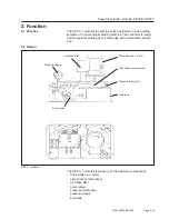
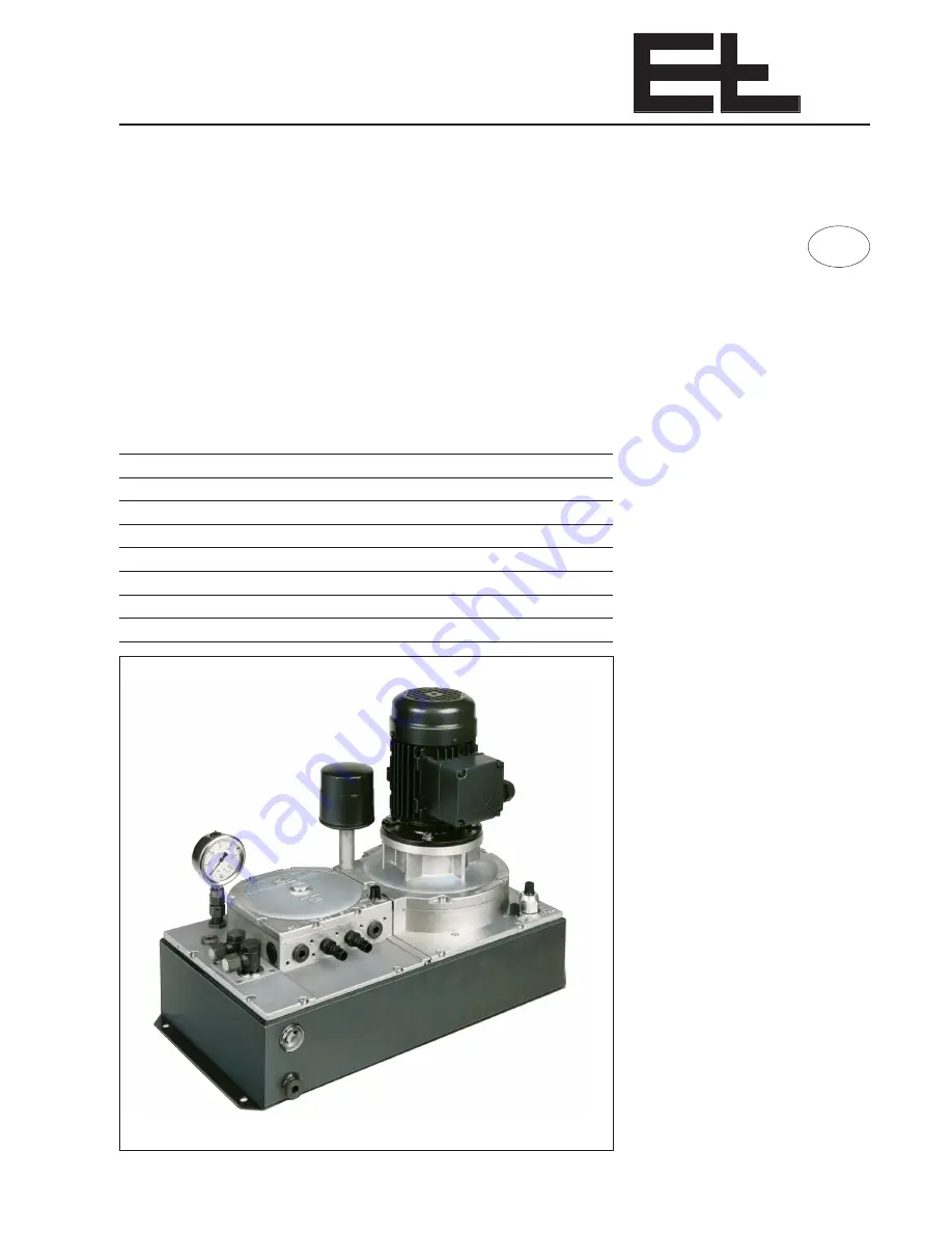
Page 3: ...ems guiding by the web edge with a pneumatic sensor FL2 2 Function 2 1 Purpose HP 03 controller 2 2 Design Side channel compressor Air intake filter Servo valve Pressure gauge Fluid tank Pressure relief valve Three phase a c motor The HP 03 controller is made up of the following components three phase a c motor side channel compressor air intake filter servo valve pressure relief valve pressure ga...

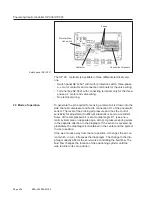
Page 4: ...pressor and fed to connection S 1 of the pneumatic sensor The level of the probing air pressure and thus the control sensitivity for adjustment to different situations is set via a restrictor Some of the compressed air is sent to diaphragm D 1 see pneu matic system plan on opposite page at top A pressure spring works in the opposite direction to the dia grapm If the sensor is covered ap propriatel...

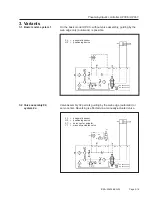
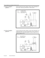
Page 5: ... B A B D 1 S 2 FL pneumatic sensor HZ positioning device P D 1 FL AIR S 2 2 OIL SC T S 1 S 2 S 1 1 S 1 2 S 2 1 P A B T HP 0360 20 bar HP 0370 30 bar A B HZ V 1 FL pneumatic sensor HZ positioning device SC servo center actuator V 1 manually actuated valve Valve assembly 02 permits guiding by the web edge automatic or servo center Reversing is effected via a manually actuated valve 3 Variants 3 1 Ba...

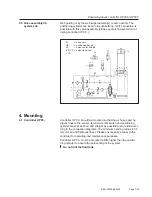
Page 6: ... with this valve assembly please quote it however when or dering controller HP 03 T T P HP 0360 20 bar HP 0370 30 bar S 1 1 S 1 2 S 2 1 S 2 2 A B S 1 FL S 2 SC Y 2 Y 3 HZ B A D 1 OIL P AIR FL pneumatic sensor HZ positioning device SC servo center actuator Y 2 Y 3 solenoid valves S 1 FL HP 0360 20 bar HP 0370 30 bar T P P T S 1 1 S 1 2 S 2 1 Y 10 Y 11 HZ S 2 Y 2 A B A B T P B A OIL D 1 AIR S 2 2 FL...

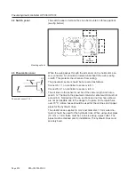
Page 7: ...e mounted so that the air hoses and hy draulic lines to the sensor return to center switch and positioning cylinder are kept as short and straight as possible and are laid accor ding to the connection diagrams The minimum bending radius is 50 mm for air and hydraulic lines Please ensure easy access to the controller for operating and maintenance purposes Controller HP 03 must be mounted a little h...

Page 8: ...the same length and not ex ceed 3 m The line to the pneumatic return to center switch must not exceed 6 m Narrowing of cross sections and narrow hose elbows are not permissible due to the danger of rupture For temperatures over 70 C silicon hoses should be used for the air lines and copper pipes for the hydraulic lines The plastic tubes supplied 6 mm inner diameter 10 mm outer dia meter should be ...

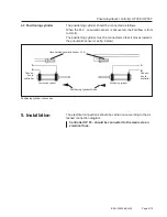
Page 9: ...it moves towards the pneumatic sensor see fig below Positioning cylinder stroke Positioning cylinder Positioning cylinder A B Connec tion to controller Uncovered pneumatic sensor FL 2 Positioning cylinder connection The electrical connections should be carried out according to the at tached connection diagram Controller HP 03 should be connected to the mains via an electrical fuse 5 Installation 4...

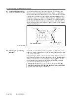
Page 10: ...o phases in the connection lead 6 Commissioning Check the direction of the positioning cylinder travel when the three phase a c motor is switched on To do so select the gui ding by web edge mode automatic The positioning cylinder or device must move the web away from the sensor when the sensor jets are covered see fig on opposite page When the air sensor is uncovered the positioning cylinder shoul...

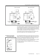
Page 11: ... center mode the servo center ac tuator must be set The command device should be set to servo cen ter mode The positioning cylinder moves until the pneumatic servo center actuator is covered by a half see fig on right If the positioning cylinder moves into an end position the connection on the servo center actuator must swapped from B to A The center position can be set by shifting the servo cente...

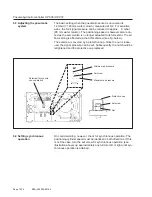
Page 12: ...rew is covered by a protective cap Once the nut is loose ned the signal pressure can be set Subsequently the nut should be retightened and the protective cap replaced On commissioning however check for synchronous operation The positioning cylinder speed must be identical in both directions If this is not the case turn the set screw for synchronous operation see illustration above up approximately...

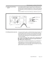
Page 13: ...he set pressure can be adjus ted see fig above By turning to the left the pressure is reduced and thus also the positioning force Adjustments should be carried out only when idling The pressure limiting valve should only be actuated when the system is at a standstill or idling It can only be turned with difficulty when under pressure We recommend you reduce the fluid pressure if no great degree of...

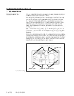
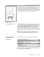
Page 14: ...le test Using a clean screwdriver sprinkle a little fluid onto a piece of white absorbent paper If a deep brown coloured spot metallic scuff or other soiling appears in the center of the stain the fluid should be changed The fluid must be changed after approx 6000 operating hours or at least once a year The fluid should only be changed at operating tem perature Once the controller is switched off ...

Page 15: ... destroy the diaphragm in the servo valve The air jets in the pneumatic sensor should be flushed out with compressed air In the case of extreme soiling the sensor should first be cleaned with petroleum ether or paraffin The hose lines may also have to be clea ned Do not clean the pneumohydraulic controller with com pressed air Compressed air will destroy the controller We recommend you keep a stoc...

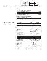
Page 16: ...data HP 0360 HP 0370 3 phase motor see sticker motor rating Operating pressure 20 bar 30 bar Pressure on cylinder when adjusted to maximum 14 bar 21 bar Pump delivery 1 5 3 l min 3 6 l min Fluid content 15 l 25 l Fluid type H LP 32 DIN 51524 ISO VG 32 DIN 51519 Temperature rise above ambient 35 C 45 C Maximum operating temperature 80 C Sound level 64 dB Sensor air pressure 5 30 mbar Weight with fl...

Reviews: