background image

Issue B – July 2010 – ETH_ANTARES_USM 


DIGITAL TECHNOLOGIES FOR A BETTER WORLD 

www.eurotech.com 


USER MANUAL

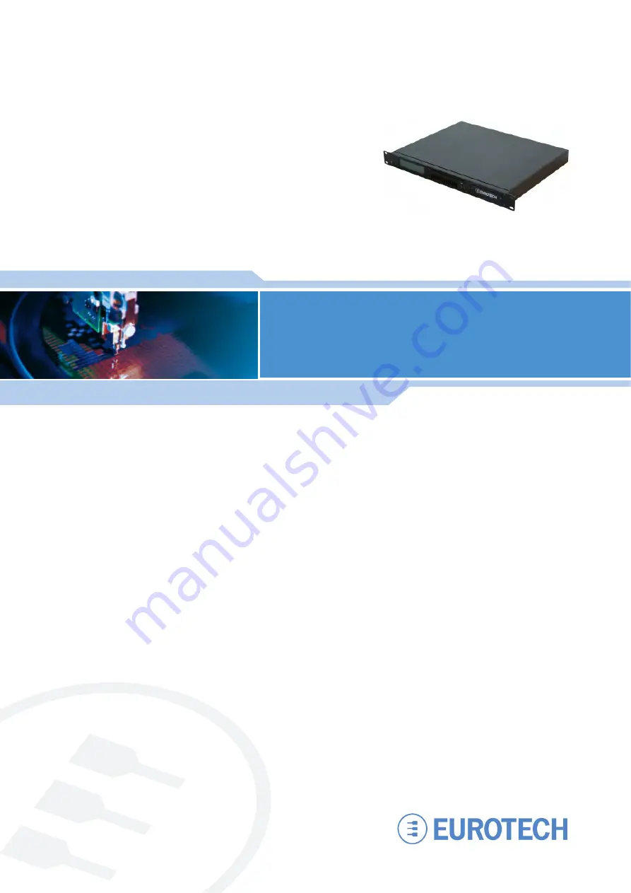
ANTARES 1U ICE

Industrial Compact Enclosure

Summary of Contents for ANTARES 1U ICE

Page 1: ...Issue B July 2010 ETH_ANTARES_USM DIGITAL TECHNOLOGIESFOR A BETTER WORLD www eurotech com USER MANUAL ANTARES 1U ICE Industrial Compact Enclosure ...

Page 2: ...RADEMARKS All trademarks both marked and not marked appearing in this document are the property of their respective owners REVISION HISTORY Issue no PCB Date Comments A 24 th May 2010 First release of manual B 23 rd July 2010 Minor updates 2010 Eurotech Ltd All rights reserved See Eurotech Worldwide Presence on the back cover for full contact details ...

Page 3: ...5 WEEE 6 RoHS 6 Technical assistance 6 Introduction 7 ANTARES 1U ICE specification 8 ANTARES ICE at a glance 9 Features of the ANTARES ICE 10 Connectors 11 Internal configuration 16 Removing and fitting the PCI Express card module 17 Tamper detect switch 19 Dimensions 20 Weight 20 EMC conformity 21 Eurotech Worldwide Presence 23 ...

Page 4: ...ns necessary for the safe operation of the equipment in your operating environment Installation in cupboards and safes In the event that the product is placed within a cupboard or safe together with other heat generating equipment ensure proper ventilation Do not operate in an explosive atmosphere Do not operate the equipment in the presence of flammable gases or fumes Operation of any electrical ...

Page 5: ... disposed of in a safe manner following the relevant COSHH regulations Damaged leaking or corroded batteries especially lithium batteries must only be handled with caution Use non conductive tools and wear suitable protection e g safety glasses rubber gloves etc All faulty batteries must be segregated in a suitable clearly marked non conductive container They must be periodically disposed of by a ...

Page 6: ...ormation In case of illicit disposal sanctions will be levied on transgressors RoHS This device including all it components subassemblies and the consumable materials that are an integral part of the product has been manufactured in compliance with the European directive 2002 95 EC known as the RoHS directive Restrictions on the use of certain Hazardous Substances This directive targets the reduct...

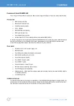
Page 7: ... Multi Writer dual Ethernet supporting 10 100 1000baseT USB ports HDMI ports SD card socket serial ports and a number of additional features for creating secure systems optional VGA 3 5mm Audio ports The system can also be fitted with two PCI express add on cards The system is available with options for multiple video outputs integrated wireless modules with location for external antenna and compl...

Page 8: ... socket under cover at rear Two serial ports Six USB 2 0 compliant ports two on front four on rear Front panel 256 x 64 pixel LCD display Auto ranging 90 265V 47 63Hz AC Flex ATX PSU DC power input option also available on request Contact Eurotech s sales team for details see page Eurotech Worldwide Presence page 23 Two PCI Express expansion slots via an internal flexible riser Two Mini PCI Expres...

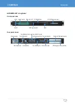
Page 9: ... RW drive 2 5 HDD access cover On off DVD eject switch USB Rear panel views Two Ethernet ports and four USB 2 0 ports Power supply Two SMA ports Lid retaining screw Two serial ports Optional VGA Audio panel M4 Earth stud External fan Two HDMI ports SD card access PCI Express card positions ...

Page 10: ... around the display that accepts customised membranes may be preferred Rear panel Position for AC or DC power supply unit M4 Earth stud Two SMA ports cabled internally to rear panel External fan pulling air out of unit Two Ethernet ports RJ45 Four USB 2 0 type A ports Two HDMI 1 3 ports Two serial ports 9 way D type SD card access retaining cover shown Two PCI Express card positions Optional panel...

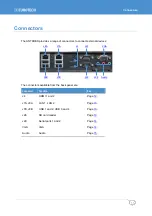
Page 11: ...8A J7A J4 J29 VGA J8B J7B J29 J28 Audio The connectors available from the back panel are Connector Function See J4 HDMI 1 and 2 Page 12 J7A J8A LAN 1 LAN 2 Page 13 J7B J8B USB 1 and 2 USB 3 and 4 Page 13 J28 SD card reader Page 13 J29 Serial ports 1 and 2 Page 14 VGA VGA Page 14 Audio Audio Page 15 ...

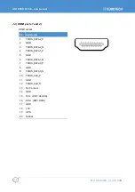
Page 12: ...rts 1 and 2 HDMI socket Pin Signal name 1 TMDS_DATA2_P 2 GND 3 TMDS_DATA2_N 4 TMDS_DATA1_P 5 GND 6 TMDS_DATA1_N 7 TMDS_DATA0_P 8 GND 9 TMDS_DATA0_N 10 TMDS_CLK_P 11 GND 12 TMDS_CLK_N 13 No Connect 14 GND 15 SCL DDC CLOCK 16 SDA DDC DATA 17 GND 18 5V 19 HPD 20 SHELL ...

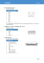
Page 13: ...uld be a CAT5 or above and include all four pairs J7B USB ports 1 and 2 and J8B USB ports 3 and 4 USB type A connector Pin Signal name 1 VBUS 2 Data 3 Data 4 Ground J28 SD card reader SD card socket Molex 67840 8001 Pin Signal name 1 Connector data line 3 2 Command response line 3 GND 4 Power supply 5 Clock 6 GND 7 Connector data line 0 8 Connector data line 1 9 Connector data line 2 9 1 2 3 4 5 6...

Page 14: ...ta RX 3 Transmit Data TX 4 Data Terminal Ready DTR 5 Ground 6 Data Set ready DSR 7 Request To Send RTS 8 Clear To Send CTS 9 Ring Indicator RI VGA CRT connector DB15 female Pin Signal name Pin Signal name 1 Red 2 Green 3 Blue 4 No connect 5 Ground 6 Ground 7 Ground 8 Ground 9 5V fused 10 Ground 11 No Connect 12 DDCSDA 13 HSYNC 14 VSYNC 15 DDCSCL 9 6 5 1 5 1 15 11 10 6 ...

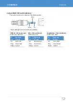
Page 15: ... LINE IN 3 5mm audio jack MIC 3 5mm audio jack Headphones 3 5mm audio jack PC99 colour light blue PC99 colour pink PC99 colour green Pin part Signal name 2 1 mode Pin part Signal name 2 1 mode Pin part Signal name 2 1 mode Tip Line in left Tip Microphone In Tip Line out left Ring Line in right Ring No Connect Ring Line out right Sleeve Ground Sleeve Ground Sleeve Ground ...

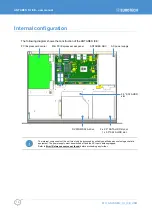
Page 16: ...access panel ANTARES SBC AC power supply DVD RW SATA drive 2 x 2 5 SATA HDD slot or 1 x 3 5 SATA HDD slot The internal components of the unit must only be accessed by suitably qualified personnel using anti static equipment The power supply must be switched off and the AC input cable unplugged Refer to Error Reference source not found before proceeding any further 3 5 SATA HDD slot ...

Page 17: ...y cables attached to installed PCI Express expansion cards 2 Unplug the flexible riser connection to the ANTARES SBC Take care to pull on the plug in connector rather than the flexible cable Connected peripheral devices or software could be damaged if the warnings are not carefully followed 3 Disconnect the tamper detect cable from front panel breakout board assembly The PCI Express module is reta...

Page 18: ...ICE_USM To fit a PCI Express card follow these steps 1 Remove the blanking plate 2 Plug the card into the riser 3 Adjust and fix the support bracket to suit 4 Tighten the retaining screw To re fit the PCI Express Module reverse the above procedure ...

Page 19: ...mper detection bit is battery backed in static RAM Using a normally open switch a tamper is detected when the switch contacts close The BIOS security setup screen provides two options for enabling a case open warning It also provides a secure chassis mode that requires the supervisor password to be entered and the chassis intrusion detection to be disabled before the board will boot to an operatin...

Page 20: ...0297 and IEC 60917 19 Rack Mounting dimensions and fits into a standard rack cabinet The rear of the unit must be supported when rack mounted Weight The weight of the unit depends on the configuration used and the optional items chosen when ordering The unit nominal weight is approximately 6kg 13 2lbs ...

Page 21: ...Harmonics EN61000 3 2 FCC Verification Part 15B Class B This equipment has been tested and found to comply with the limits for a Class B digital device pursuant to part 15 of the FCC Rules These limits are designed to provide reasonable protection against harmful interference when the equipment is operated in a commercial environment This equipment generates uses and can radiate radio frequency en...

Page 22: ...Peak Sawtooth Peak Acceleration 40g Pulse Duration 11ms No of shocks 3 in each direction of 3 mutually perpendicular axes Random vibration test In accordance with MIL STD 810F Method 514 5 Category 20 Figure 514 5C 1 Frequency Range 10Hz to 500Hz Severity 1 04g vertical axis 0 204g transverse axis 0 74g longitudinal axis Duration 2 hours in each axis ...

Page 23: ...rotech com Web www eurotech com Finland EUROTECH Tel 358 9 477 888 0 Fax 358 9 477 888 99 E mail sales fi eurotech com E mail support fi eurotech com Web www eurotech com ASIA Japan ADVANET Tel 81 86 245 2861 Fax 81 86 245 2860 E mail sales advanet co jp E mail tsupport advanet co jp Web www advanet co jp India EUROTECH Tel 91 80 43 35 71 17 E mail sales in eurotech com E mail support in eurotech ...

Page 24: ...www eurotech com EUROTECH HEADQUARTERS Via Fratelli Solari 3 a 33020 Amaro Udine ITALY Phone 39 0433 485 411 Fax 39 0433 485 499 For full contact details go to www eurotech com contacts ...

Reviews: