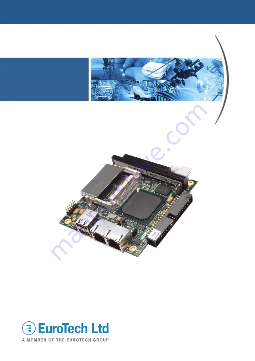
background image


VULCAN 

Intel IXP425 XScale based 

PC/104 Single Board Computer 

Technical Manual


Summary of Contents for VULCAN-533-M64-F16

Page 1: ...VULCAN Intel IXP425 XScale based PC 104 Single Board Computer Technical Manual ...

Page 2: ...able effort to repair the product or replace it with an identical variant Eurotech reserves the right to replace the returned product with an alternative variant or an equivalent fit form and functional product Delivery charges will apply to all returned products Please check www eurotech ltd co uk support for information about Product Return Forms Trademarks ARM and StrongARM are registered trade...

Page 3: ...nments 18 VULCAN address map 19 Expansion bus 21 PCI bus 22 Real time clock 23 Tamper detect circuit 24 Watchdog timers 25 Silicon serial number 27 Memory 28 Interrupt assignments 29 General purpose I O 30 Data communications 31 Expansion interfaces 35 Power and power management 37 Power supplies 37 Power management 38 Connectors LEDs and jumpers 41 Connectors and headers 42 Jumpers 49 Status LEDs...

Page 4: ...terface operating at 133MHz two UART interfaces and a watchdog timer The VULCAN board offers a wide range of features that make it ideal for embedded communications and networking solutions The board is available in the following standard variants VULCAN 533 M64 F16 Intel IXP425 533MHz CPU Mx 64M DRAM Fx 16M FLASH VULCAN 533 M64 F32 Intel IXP425 533MHz CPU Mx 64M DRAM Fx 32M FLASH An industrial te...

Page 5: ...ssue D 5 VULCAN at a glance 2 Ethernet ports 2 USB2 0 ports Digital I O Tamper connector CompactFlash 4 serial ports Intel Xscale IXP425 533MHz network processor Flash memory silicon disk Power inc battery input 2 USB2 0 ports SDRAM 8 16 Bit PC 104 interface ...

Page 6: ... Flash with Flash access LED SRAM battery backed disk 256KBytes of SRAM battery backed off board Serial ports 4 x UART fast serial ports 2 x IXP425 UARTs 921KBaud RS232 2 x 16550 compatible UARTs 115 2 KBaud 1 x RS232 This port has a factory build option for TTL signal levels 1 x RS422 485 jumper selectable 40 pin 0 1 Box header USB support USB 2 0 host controller 4 x USB 2 0 ports supporting 480M...

Page 7: ...CF cards 16 bit PC 104 interface Date time support Real time clock battery backed off board or on board supercap Tamper detect Tamper detect circuit implemented using DS1302 RTC Unique ID number Implemented using DS2401 silicon serial number Watchdog timer 2 WD timers Internal to IXP425 External with software selectable timeout 1ms 60s General I O 16 x general purpose I O Eight inputs 5V tolerant ...

Page 8: ...ices On board regulators for CPU core and I O voltages Power monitor generates reset on low voltage condition Super capacitor On board GoldCap Provides RTC backup for up to 5 days Mechanical Standard PC 104 form factor 95mm x 90mm Environmental Operating temperature Commercial 20 C to 70 C 4o F to 158o F Industrial 40 C to 85 C 40o F to 185o F ...

Page 9: ...duction 2007 Eurotech Ltd Issue D 9 VULCAN support products The VULCAN is supported by the VULCAN ICE Industrial Compact Enclosure This is a simple low cost aluminum enclosure that provides easy connection to all on board features ...

Page 10: ...This includes storing boards in appropriate anti static packaging and wearing a wrist strap when handling Packaging Should a board need to be returned to Eurotech please ensure that it is adequately packed preferably in the original packing material Electromagnetic compatibility EMC The VULCAN is classified as a component with regard to the European Community EMC regulations and it is the user s r...

Page 11: ...es information about all aspects of the board Conventions Symbols The following symbols are used in this guide Symbol Explanation Note information that requires your attention Tip a handy hint that may provide a useful alternative or save time Caution proceeding with a course of action may damage your equipment or result in loss of data Jumper fitted on pin A Jumper fitted on pin B Jumper is fitte...

Page 12: ...cific operating system and the VULCAN Industrial Compact Enclosure ICE Technical Manual Other manuals are referred to from time to time These are provided on the CD ROM that accompanies your Development Kit The Quickstart Manual for the selected operating system explains how to set up and start using the board Please work through it before reading this manual You will then have a working VULCAN sy...

Page 13: ...via a 40 way boxed header The pin assignment of these headers has been arranged to enable a 9 way IDC D Sub plug to be connected directly to the cable For pin assignments and connector details see J7 COMS ports and JTAG connector page 46 A suitable cable for COM1 is provided as part of the Development Kit The D Sub connector on this cable is compatible with the standard 9 way connector on a deskto...

Page 14: ... The peripheral PC 104 board should normally be plugged into the bottom side of the board For further details see PC 104 interface page 36 and J8 J10 PC 104 connectors page 47 Before you power up the system check that the jumper settings on the add on cards for I O address and IRQ settings do not conflict with each other The ISA interface on the VULCAN does not support DMA For PC 104 interrupt use...

Page 15: ...iagram The following diagram illustrates the functional organisation of the VULCAN Intel IXP425 Network Processor RJ45 33MHz Expansion Bus Digital I O Battery backed SRAM 256KBy Flash 16 32MBy 1xRS232 TTL 1xRS422 RS485 2x16550 UART 115 2 KBaud H e a d e r WAN Ethernet PHY0 10 100Mb s WAN Ethernet PHY1 10 100Mb s 2xUART 921KBaud 2xRS232 Power Supplies 5V to 3V3 1V3 2V5 Reset Circuit PCI BUS SDRAM 3...

Page 16: ...thentication hardware acceleration High speed UART 921KBaud Console UART 921KBaud Internal bus performance monitoring unit 16 GPIO Four internal timers including watchdog timer Available in 266MHz 400MHz and 533MHz speed variants 492 pin PBGA packaging The VULCAN design supports all speed variants of the Intel IXP425 processor The standard variant of VULCAN uses the 533MHz version of Intel IXP425 ...

Page 17: ...ork processor implements DES 3DES and AES data encryption algorithms in addition to SHA 1 and MD5 authentication algorithms which are typically used in applications such as VPNs Virtual Private Networks Using the NPE for dedicated hardware acceleration enables the processing of cryptography and authentication algorithms to be offloaded from the Intel XScale core The Intel XScale core API calls all...

Page 18: ...Q3 Input Rising edge PC 104 interrupt 6 ISA_IRQ4 Input Rising edge PC 104 interrupt 7 ISA_IRQ5 Input Rising edge PC 104 interrupt 8 ISA_IRQ6 Input Rising edge PC 104 interrupt 9 ISA_IRQ7 Input Rising edge PC 104 interrupt 10 ISA_IRQ10 Input Rising edge PC 104 interrupt 11 ISA_IRQ11 Input Rising edge PC 104 interrupt 12 ISA_IRQ12 Input Rising edge PC 104 interrupt Interrupt assignments page 29 13 R...

Page 19: ...0_2000 C800_2FFF 1KB Internal bus performance monitoring unit C800_3000 C800_3FFF 1KB Interrupt controller C800_4000 C800_4FFF 1KB GPIO controller C800_5000 C800_5FFF 1KB Timers C800_6000 C800_6FFF 1KB WAN HSS NPE NOT connected on VULCAN SBC C800_7000 C800_7FFF 1KB Ethernet NPE A not user programmable C800_8000 C800_8FFF 1KB Ethernet NPE B not user programmable C800_9000 C800_9FFF 1KB Ethernet MAC...

Page 20: ... 1000_0000 RedBoot reconfigures the memory map so that Expansion bus starts at address 5000_0000 and SDRAM starts at address 0000_0000 The largest SDRAM memory size supported by the Intel IXP4XX product line processors is 256MB The actual memory implemented in any given configuration is aliased repeated to fill the 1GB SDRAM address space Due to aliasing all of the SDRAM is accessible even when th...

Page 21: ... address spaces are listed in the following table Chip select address spaces relate to the expansion bus base address given in the main memory map Chip select Assignment Size Address space relative to base address Data bus width Access CS0 Flash 16MB 0x00000000 0x00FFFFFF 16b D 15 0 R W CS1 Flash F32 variant 16MB 0x01000000 0x01FFFFFF 16b D 15 0 R W CS2 SRAM 256KB 0x02000000 0x0203FFFF 8b D 7 0 R ...

Page 22: ... signal mapped to the particular PCI device IDSEL signal is asserted Device IDSEL signal PCI interrupt mapping USB 2 0 host controller PCI_AD31 USB_INTA GPIO2 CardBus controller PCI_AD30 CF_INTB GPIO3 PCI bus devices can be reset using bit 4 of WD setup register The register is memory mapped and located on the expansion bus CS5 The following table shows the WD setup register bit definitions Bits D...

Page 23: ... first year 1ppm in the year after and decreases logarithmically in subsequent years The following IXP425 GPIO pins are used to emulate the serial I O interface to the DS1302 RTC IXP425 GPIO pin Function GPIO 0 RTC_RST GPIO 1 RTC_CLK GPIO 13 RTC_D The DS1302 RTC also contains 31 bytes of RAM which can be used for any data that must be recoverable on power up RTC is backed by an external battery or...

Page 24: ...of 5 days The tamper detect software stores a unique pattern in the RTC RAM which is cleared when the tamper detect system is activated Any tamper detect activity in either a powered or non powered situation cuts the power supply to the RTC and clears the contents of the DS1302 RAM and a CLOCK HALT bit within the device This single bit is not battery backed and is guaranteed to activate once the R...

Page 25: ...10ms 30ms 100ms 1s 10s and 60s The board is reset when timeout occurs The MAX6369 WDT can be programmed using the WD setup register provided within the CPLD The register is memory mapped and located on the expansion bus CS5 The WDT is disabled upon reset and remains so until enabled by the software The following table shows the WD setup register bit definitions Bits Description 7 5 Not used 4 PCI_...

Page 26: ...e description 2007 Eurotech Ltd Issue D 26 The following table shows the definitions for various watchdog timeout periods WDSET2 WDSET1 WDSET0 tDELAY tWD 0 0 0 1ms 0 0 1 10ms 0 1 0 30ms 0 1 1 Disabled 1 0 0 100ms 1 0 1 1s 1 1 0 10s 1 1 1 60s ...

Page 27: ...silicon serial number The DS2401 consists of a factory lasered 64 bit ROM that includes a unique 48 bit serial number an 8 bit CRC and an 8 bit family code 01h Data is transferred serially via the 1 Wire protocol that requires only a single data lead and a ground return The IXP425 processor s pin GPIO14 is used to emulate the serial 1 Wire interface to the DS2401 ...

Page 28: ... support the 256 megabit Flash device F32 VULCAN variant The Flash memory array is divided into equally sized symmetrical sectors that are 32 Kword in size A 128 megabit device contains 256 sectors and a 256 megabit device contains 512 sectors Whenever you access the Flash memory the Flash access LED illuminates SDRAM interface VULCAN supports 64 Mbytes of SDRAM The SDRAM is configured as 16M x 32...

Page 29: ...rrupts The following table lists the IXP425 signal pins used for external interrupt inputs IXP425 pin Signal Active Peripheral GPIO 2 USB_INTA Low USB controller GPIO 3 CF_INTB Low CF controller GPIO 4 UART_IRQ Low UART GPIO 5 ISA_IRQ3 Rising edge PC 104 GPIO 6 ISA_IRQ4 Rising edge PC 104 GPIO 7 ISA_IRQ5 Rising edge PC 104 GPIO 8 ISA_IRQ6 Rising edge PC 104 GPIO 9 ISA_IRQ7 Rising edge PC 104 GPIO ...

Page 30: ...at address offset 0x04000000 0x54000000 The general purpose inputs are 5V tolerant and the outputs can sink and source up to 24mA 3 3V The following table shows the bit definitions Bits Description 7 0 IN 7 0 GP inputs on read access OUT 7 0 GP outputs on write access Hex Offset Address 0x04000000 Reset Hex Value 0x00 Access Read write This is illustrated by the following diagram IXP425 Buffer J3 ...

Page 31: ...s and the availability of particular USB peripherals can be found at www usb org Please refer to the ISP1561 datasheet on the Development Kit CD for details about the Hi Speed USB PCI host controller 10 100 BaseTX Ethernet The IXP425 network processor provides two 10 100 BaseT interfaces with MAC and complies with both the IEEE802 3u 10 100 BaseTX and the IEEE 802 3x full duplex flow control speci...

Page 32: ... Intel IXP425 technical documentation only to make a distinction between the two UART interfaces Both UART Interfaces exhibit exactly the same features The term Console doesn t presume the use of this UART by user s software Further details about each of these COMs ports is provided below COM1 RS232 interface Uses the High speed UART in the IXP425 with 64 bytes deep transmit and receive buffers Th...

Page 33: ... B5 must be fitted if the board is at the end of the network See JP1 Jumper header page 49 for details RS485 This is a half duplex interface that provides combined TX and RX signals Connector J7 pin 5 provides TX RX and pin 6 provides TX RX A ground connection is also required for this interface The maximum cable length for this interface is the same as RS422 4000ft but RS485 supports up to 32 tra...

Page 34: ...O POINT RS422 MULTI DROP Number of Wires 5 Transmitters Enabled always Receivers Enabled always Duplex Mode full LINKS A2 A1 B2 B1 Number of Wires 5 Transmitters Enabled active RTS Receivers Enabled always Duplex Mode full LINKS A2 A1 B2 B1 Number of Wires 3 Transmitters Enabled active RTS Receivers Enabled always Duplex Mode half LINKS A2 A3 B2 B3 ...

Page 35: ... I O cards including serial cards Ethernet cards fax modem cards digital phone cards USB barcode scanners Bluetooth 802 11b wireless LAN wireless digital cell phone cards etc For more details about CF standards and availability of particular CF peripherals see www compactflash org The CF card provides high capacity data storage and I O functions that electrically comply with the Personal Computer ...

Page 36: ...he IXP425 processor The PC 104 bus signals are compatible with the ISA bus electrical timing definitions DMA and bus mastering are not supported on VULCAN s PC 104 interface For details about PC 104 interrupts see Interrupt assignments page 29 The VULCAN provides 5V to a PC 104 add on board via the J8 and J10 connectors If a PC 104 add on board requires a 12V supply then 12V must be supplied to th...

Page 37: ...2 8V to 3 3V can be used to backup the DS1302 RTC and the SRAM The external battery supplies power to the battery backup circuit only when there is no 5V supply to the board A battery backup supervisor circuit is used to enable battery switchover To use an external battery connect its and terminals across J9 pins 3 VBAT and 2 GND respectively For connector and mating connector details see J9 Power...

Page 38: ... of the following occur Receive data start bit Change of state on CTS DSR CD RI Data is being loaded into transmit FIFO If the part was awakened by one of the above conditions it returns to sleep mode automatically after the condition has cleared Using the PowerSave feature of XR16L2551 it is possible to reduce power consumption even further The L2551 enters PowerSave mode when the PWRSAVE pin is ...

Page 39: ...lowest power possible The device can be put into a low power state via Register 0 of LXT973 as well as a near zero power state with the power down pin When in power down mode the device is not capable of receiving or transmitting packets The lowest power operation is achieved using the global power down pin This active high pin powers down every circuit in the device including all clocks Individua...

Page 40: ...t The ISP1561 USB Host Controller supports four USB ports Two of the ports can be disabled if not used by setting the SEL2PORTS pin high MFUNC4 pin on the PCI1520 device should be configured as GP output and can be used to control the SEL2PORTS pin of the ISP1561 controller Disabling two of the ports can reduce the power consumption of the VULCAN by up to 165mW MFUNC4 SEL2PORTS ISP1561 Operation S...

Page 41: ...l Connectors LEDs and jumpers 2007 Eurotech Ltd Issue D 41 Connectors LEDs and jumpers The following photo shows the location of the connectors LEDs and jumpers on the VULCAN J1 JP2 J2 J3 J4 J11 J6 Flash LED J7 JP1 J9 J8 J10 ...

Page 42: ... connector page 43 J2 USB J2 USB connector page 43 J3 GPIO J3 GPIO connector page 44 J4 USB J4 USB header page 44 J6 CompactFlash Type I II J6 CompactFlash connector page 45 J7 Serial and JTAG J7 COMS ports and JTAG connector page 46 J8 64 way PC 104 expansion J8 J10 PC 104 connectors page 47 J9 Power battery external reset J9 Power connector page 48 J10 40 way PC 104 expansion J8 J10 PC 104 conne...

Page 43: ...TX0 1A TX1 2B TX0 2A TX1 3B RX0 3A RX1 4B N C 4A N C 5B N C 5A N C 6B RX0 6A RX1 7B N C 7A N C 8B N C 8A N C 9B LED0_SPEED 9A LED1_SPEED 10B 3V3 10A 3V3 11B LED0_LINK 11A LED1_LINK 12B 3V3 12A 3V3 J2 USB connector USB type A dual stacked connector Suyin 020122MR008S236ZA Pin Signal name Pin Signal name 1 VBUS1 1 VBUS2 2 D1 2 D2 3 D1 3 D2 4 GND 4 GND LINK ACT 100 Pin no 8 Pin no 1 typ per typ per p...

Page 44: ...FCI 77138 001 Pin Signal name Pin Signal name 1 5V 2 5V 3 IN0 4 IN1 5 IN2 6 IN3 7 IN4 8 IN5 9 IN6 10 IN7 11 GND 12 GND 13 OUT0 14 OUT1 15 OUT2 16 OUT3 17 OUT4 18 OUT5 19 OUT6 20 OUT7 J4 USB header Neltron 2213S 10G 10 way 2 54mm 0 1 x 2 54mm 0 1 dual row header Mating connector Molex 51110 1050 Mating connector crimps Molex 50394 8051 Pin Signal name Pin Signal name 1 VBUS3 2 VBUS4 3 D3 4 D4 5 D3 ...

Page 45: ... Pin Signal name 1 GND 2 D03 3 D04 4 D05 5 D06 6 D07 7 CE1 8 A10 9 OE 10 A09 11 A08 12 A07 13 3 3V 14 A06 15 A05 16 A04 17 A03 18 A02 19 A01 20 A00 21 D00 22 D01 23 D02 24 IOCS16 25 CD2 26 CD1 27 D11 28 D12 29 D13 30 D14 31 D15 32 CE2 33 VS1 GND 34 IORD 35 IOWR 36 WE 37 RDY BSY 38 3 3V 39 CSEL GND 40 N C 41 RESET 42 WAIT 43 INPACK 44 REG 45 N C 46 N C 47 D08 48 D09 49 D10 50 GND ...

Page 46: ...tor FCC 71600 040 Pin Signal name Pin Signal name 1 3V3 2 JTG_TRST 3 JTG_TDO 4 JTG_TDI 5 RX3 TX3 6 RX3 TX3 7 RX3 8 RX3 9 GND 10 GND 11 N C 12 N C 13 RXD1 14 RTS1 15 TXD1 16 CTS1 17 GND 18 GND 19 GND 20 JTG_SRST 21 DCD2 22 DSR2 23 RXD2 24 RTS2 25 TXD2 26 CTS2 27 DTR2 28 RI2 29 GND 30 JTG_TMS 31 N C 32 N C 33 RXD0 34 RTS0 35 TXD0 36 CTS0 37 N C 38 N C 39 GND 40 JTG_TCK As viewed from the connector p...

Page 47: ...3 DRQ2 7 D2 NC 8 D1 NC 0 GND GND 9 D0 12V 1 MEMCS16 SBHE 10 IOCHRDY KEY 2 IOCS16 LA23 11 AEN SMEMW 3 IRQ10 LA22 12 A19 SMEMR 4 IRQ11 LA21 13 A18 IOW 5 IRQ12 LA20 14 A17 IOR 6 IRQ15 LA19 15 A16 DACK3 1 7 IRQ14 LA18 16 A15 DRQ3 8 DACK0 1 LA17 17 A14 DACK1 1 9 DRQ0 MEMR 18 A13 DRQ1 10 DACK51 MEMW 19 A12 REFSH1 11 DRQ5 D8 20 A11 8MHz Clk 12 DACK6 1 D9 21 A10 IRQ7 13 DRQ6 D10 22 A9 IRQ6 14 DACK7 1 D11 ...

Page 48: ...tery backup supply for the 256Kbyte static RAM and the Dallas DS1302 real time clock 12V connection defined but is not required for the VULCAN under normal operation It can be used to supply 12V to the PC 104 stack if required J11 Tamper detect connector PH200 series 3 pin 2mm boxed header right angle Toby PH200 03 R Mating connector PH200 Series 2mm housings crimps Toby PH200 03H J11 provides the...

Page 49: ...er The user selectable jumper header JP1 is used to choose between RS422 and RS485 options and termination resistor options For more details see COM4 RS422 485 interface page 33 The default position of the jumpers are shown in the following diagram The following tables describe the jumper locations in more detail A5 B5 Description RS485 TX RX RS422 TX line termination resistor 120Ω connected Only ...

Page 50: ...120Ω disconnected A2 B2 Description RS422 full duplex RS485 half duplex JP2 Jumper header This user selectable jumper header is used to choose between the external battery and on board Supercap for RTC and SRAM power backup JP2 Description Supercap connected power backup for RTC only External battery connected power backup for RTC and SRAM A4 B4 A4 B4 Default setting A1 A2 B1 B2 A2 A3 B2 B3 A1 A2 ...

Page 51: ... used pins 1 and 2 of connector J11 should be shorted by jumper to enable normal operation of the DS1302 RTC as shown in the following photo VULCAN Pins 1 and 2 are on the side closest to the power connector Status LEDs There is a single status LED on the VULCAN This indicates when on board Flash memory silicon disk is being accessed ...

Page 52: ... buyer Eurotech s entire liability in respect of the boards or systems is as set out in Eurotech s standard terms and conditions of sale If you intend to write your own low level software you can start with the source code on the disk supplied This is example code only to illustrate use on Eurotech s products It has not been commercially tested No warranty is made in respect of this code and Eurot...

Page 53: ...ne 50 pin type I II CompactFlash Socket USB Quad channel v2 0 support Ethernet Dual IEEE802 3u support Temperature Operating 20o C to 70o C 4o F to 158o F commercial 40o C to 85o C 40o F to 185o F industrial Humidity 10 to 90 RH non condensing Real time clock Accuracy 1minute month Software RedBoot bootloader Power requirement 5V 5 4 5W maximum consumption without CF or USB devices fitted 3 5W typ...

Page 54: ... J10 J9 J11 JP1 JP2 0 00 24 13 10 16 29 21 85 09 90 00 50 01 5 08 5 68 6 35 0 00 5 08 7 62 12 70 25 72 27 94 1 59 96 00 0 00 8 78 17 78 33 53 46 56 59 38 67 69 82 63 85 47 90 83 84 20 0 00 24 45 83 82 94 72 76 12 4 76 7 00 7 94 1 10 4 66 2 81 A A A Ø3 18 FOUR A HOLES A Units of measurement mm All connector dimensions taken from pin 1 ...

Page 55: ...endor information and available add on products www PC 104 org USB information Universal Serial Bus USB specification and product information www usb org CompactFlash Association CompactFlash CF specification and product information www compactflash org Intel Intel XScale IXP425 processor documentation www intel com Philips ISP1561 USB 2 0 Host Controller documentation www philips com Texas Instru...

Page 56: ...echnical Manual Appendix D Reference information 2007 Eurotech Ltd Issue D 56 Exar Exar XR16C2551 DUART documentation www exar com Maxim Maxim DS1302 RTC and DS2401 Serial Number documentation www maxim ic com ...

Page 57: ...troller Interface EMC Electromagnetic Compatibility ESD Electrostatic Discharge FIFO First In First Out GPIO General Purpose Input Output ICE Industrial Compact Enclosure IO Input Output ISA Industry Standard Architecture JTAG Joint Test Access Group LAN Local Area Network LED Light Emitting Diode MAC Media Access Control MD5 Message Digest 5 MIPS Million Instructions Per Second µP Microprocessor ...

Page 58: ...c Random Access Memory SDRAM Synchronous Dynamic Random Access Memory TTL Transistor Transistor Logic UART Universal Asynchronous Receiver Transmitter USB Universal Serial Bus VAC Voltage Alternating Current VDC Voltage Direct Current VPN Virtual Private Network WAN Wide Area Network WDT Watchdog Timer ...

Page 59: ...mper detect 24 clock 7 23 generator 40 real time 53 code source 52 COM 32 COM1 32 53 COM2 33 38 53 COM3 32 53 COM4 33 38 53 CompactFlash 7 13 35 53 55 connector 45 COMs Ports connector 46 connector 41 CompactFlash 45 COMs Ports 46 ethernet 43 GPIO 44 JTAG 46 PC 104 47 power 48 tamper detect 48 USB 43 contact details 52 D diagram 54 dimensions 53 DS1302 7 DS2401 7 E electromagnetic compatibility 10...

Page 60: ...7 connector 46 interface 36 jumper 41 headers 49 locations 49 L LAN 13 LED 31 41 51 lid removing 4 link tamper 51 Linux 12 28 M map address 19 MAX6369 25 Maxim Integrated Products Inc 56 mechanical diagram 54 memory 6 28 53 Flash 28 microprocessor 53 motion control 14 N network 7 processor engine 17 NPE 17 O outputs 30 P PC 104 7 14 36 connector 47 consortium 55 modules 14 PCI bus 22 PCI1520 35 pe...

Page 61: ...1 silicon disk 6 28 serial number 27 sleep mode 38 socket CompactFlash 13 source code 52 SRAM 6 28 53 Standard Microsystems Corporation 55 static 10 RAM 28 support technical 52 system memory 6 T tamper detect 7 24 detect connector 48 link 51 tamper detect 4 technical support 52 temperature 8 53 timer watchdog 7 25 TPS2210A 39 U UART 6 33 USB 6 13 55 channel 31 connector 43 header 44 Host Controlle...

Reviews: