background image

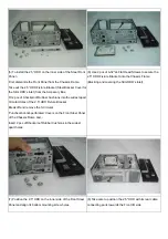
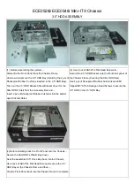
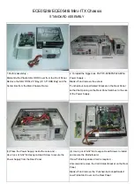
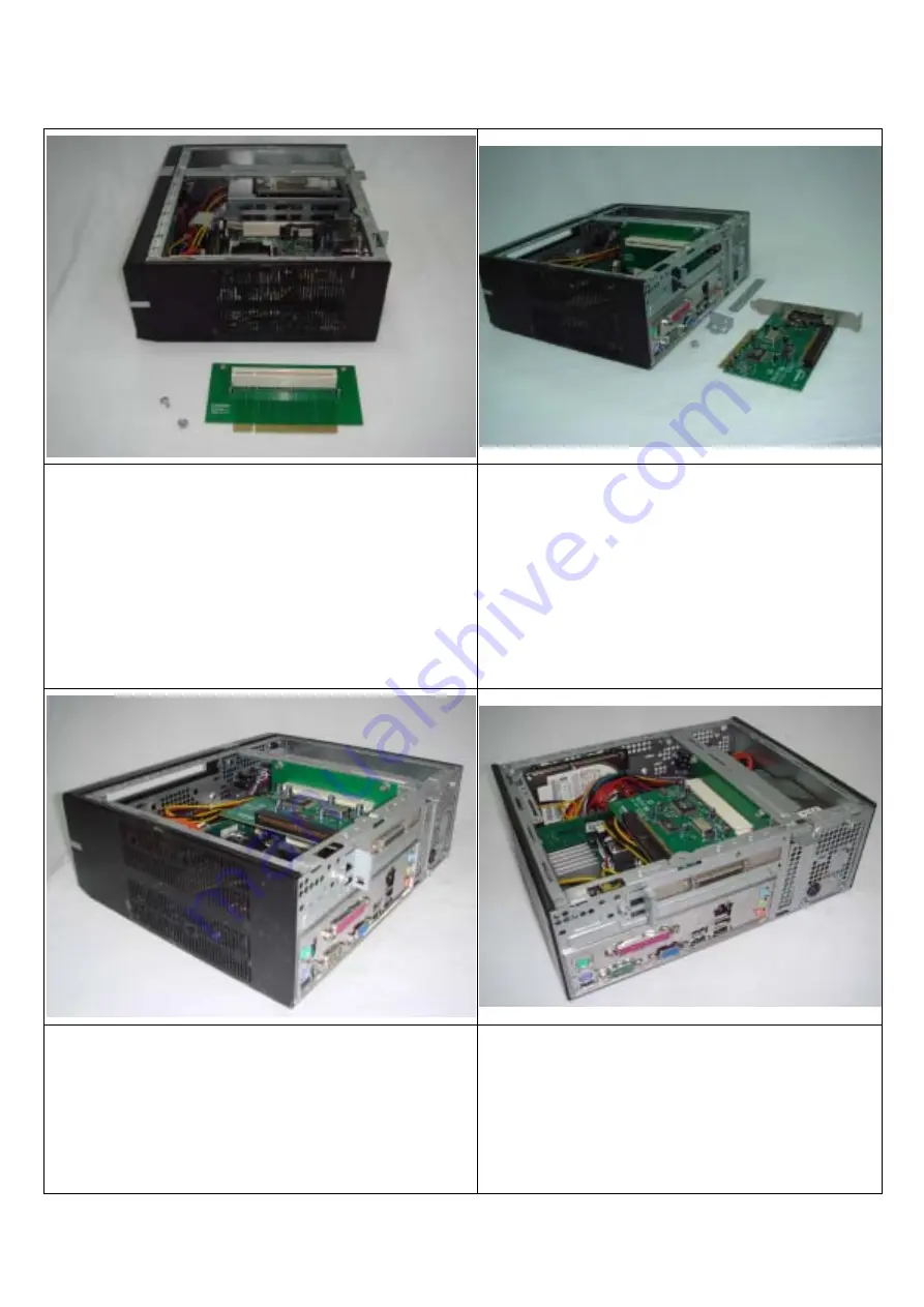
ECE0528i/ECE0548i Mini-ITX Chassis 

RISER CARD & FRONT 2.5” HDD ASSEMBLY 

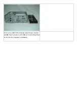
(1) With Riser Card Expansion system integration, -   

The Slim ODD+2.5”HDD Bay and/or 3.5” HDD Bay are no 

longer installable due to space limitation in the smaller 

dimensioned Mini-ITX Chassis.   


(2) To install the Riser Card, - 

Break off and remove the ‘Punched-but-not-perforated’ 

Slot Cover (For Standard PCI Card) from the Rear Panel, 

Unscrew and take out the Card Holder Bracket.   

Insert the Riser Card into the Motherboard’s PCI Slot and, 

Use 2 pcs of 6-32*L6 Hexagon Head Screws to secure the 

Riser Card on the Center Bar.   


(3) Insert your Expansion Card horizontally into the PCI Slot of 

the Riser Card.   

Fit back the Card Holder Bracket on the Rear Panel and, -   

Use 1 pc of 6-32*L6 Hexagon Head Screw secure the Card 

Holder Bracket on the Rear Panel.   

(4) With Riser Card expansion system integration, - 

1 pc of 2.5" HDD is installable on the inner side of the Steel 

Front Panel.  

Note: This installation of the 2.5" HDD would obstruct and 

invalidate the Card Reader integration.   


Summary of Contents for ECE0528i

Page 1: ...t the Card Holder Bracket Insert the Riser Card into the Motherboard s PCI Slot and Use 2 pcs of 6 32 L6 Hexagon Head Screws to secure the Riser Card on the Center Bar 3 Insert your Expansion Card hor...

Page 2: ...eak off and remove the 3 Circular Punched but not perforated Covers on the Front Steel Panel of the Chassis Frame and Insert 2 pcs of Shockproof Rubber Cushions in the widest apart holes 6 Use 2 pcs o...

Page 3: ...9 Use 4 pcs of M3 0 5 L8 Hexagon Head Screws included with EMI Clips to secure the 2 5 HDD on the Front Steel Panel from the front to complete the installation...

Page 4: ...t apart Circular Holes 2 Use 2 pcs of 6 32 L4 Flat Head Screws to Secure the 2 5 HDD Bracket onto the front steel panel of the Chassis Frame Covering the Slim ODD Inlet Use 4 pcs of Shockproof Rubber...

Page 5: ...not perforated Bracket on the Rear Panel so that the Opening on the Rear Panel matches to the size of the Power Supply 3 Place the Power Supply inside the case and Use 3 pcs of 6 32 L6 Hexagon Head S...

Page 6: ...cure it on the Main Chassis Frame with 2 pcs of 6 32 L4 Flat Head Screws 7 The Slim ODD Bay is designed with a detachable 2 5 HDD Bay to match multiple Motherboards systems 8 Use 4 pcs of M2 0 4p L3 F...

Page 7: ...GCLF D945GCLF2 Motherboards Only the Slim ODD Bay is used 11 For the system integration of DC45FC Motherboard The 2 5 HDD must be secured in the 2 5 HDD Bay and Its position must be shifted to the rig...

Page 8: ...only the Slim ODD Bay is used there is internal space to allow the insertion of Low Profile Expansion Card 15 When both the Slim ODD 2 5 HDD Bay are used The 2 5 HDD would interfere with the Low Profi...

Reviews: