Evolution EFD1000, Pilot'S Manual
The Evolution EFD1000 Pilot's Manual is an essential guide for users of this advanced flight display system. Easily download the manual for free from our website to ensure you have all the necessary information for safe and efficient operation of your EFD1000.
Share
Download


Reviews:
No comments
Related manuals for EFD1000
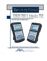
E20/20
Brand: AEA Technology, Inc. Pages: 126

LX Flarm Red Box
Brand: LX Navigation Pages: 16

G1000 NAV III
Brand: Garmin Pages: 248
HUSSMANN SMED153
Brand: Panasonic Pages: 41
C4667PW
Brand: 3M Pages: 727

GS-GH5
Brand: Lamp Pages: 4

VOLKSLOGGER
Brand: Garrecht Avionik Pages: 43

FCC-4
Brand: Federal Pages: 17

RS-CN-0250
Brand: Omcan Pages: 20

BASIA 2
Brand: Igloo Pages: 52

ST3400
Brand: Sandel Pages: 42

233276
Brand: Arktic Pages: 92


