
CAUTION
MODELS
VCDD090
I
• VCDD150
I
Page 1
READ AND SAVE THESE INSTRUCTIONS
TO REDUCE THE RISK OF FIRE, ELECTRICAL SHOCK, OR
INJURY TO PERSONS, OBSERVE THE FOLLOWING:
1. Use this unit only in the manner intended by the manufac-
turer. If you have questions, contact the manufacturer at the
address or telephone number listed in the warranty.
2. Before servicing or cleaning unit, switch power off at service
panel and lock the service disconnecting means to prevent
power from being switched on accidentally. When the
service disconnecting means cannot be locked, securely
fasten a prominent warning device, such as a tag, to the
service panel.
3. Installation work and electrical wiring must be done by a
qualified person(s) in accordance with all applicable codes
and standards, including fire-rated construction codes and
standards.
4. Sufficient air is needed for proper combustion and exhaust-
ing of gases through the flue (chimney) of fuel burning
equipment to prevent backdrafting. Follow the heating
equipment manufacturer’s guideline and safety standards
such as those published by the National Fire Protection
Association (NFPA), and the American Society for Heating,
Refrigeration and Air Conditioning Engineers (ASHRAE),
and the local code authorities.
5. When cutting or drilling into wall or ceiling, do not damage
electrical wiring or other hidden utilities.
6. Ducted fans must always be vented to the outdoors.
7. To reduce the risk of fire, use only metal ductwork.
8. If this unit is to be installed over a tub or shower, it must be
marked as appropriate for the application and be connected
to a GFCI (Ground Fault Interrupter) - protected branch
circuit.
9. Never place a switch where it can be reached from a tub or
shower.
10. This unit must be grounded.
1. For general ventilation use only. Do not use to exhaust
hazardous or explosive materials and vapors.
2. To avoid motor bearing damage and noisy and/or unbal-
anced impellers, keep drywall spray, construction dust, etc.
off power unit.
3. Please read specification label on product for further
information and requirements.
WARNING
IN-LINE
VENTILATORS • 120V
TABLE OF CONTENTS
This manual is divided into sections as follows:
•
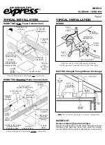
“TYPICAL INSTALLATION”
This section shows a common installation in new and
existing frame construction.
- Mounting (New Construction)
- Mounting (Existing Construction)
- Wiring
- Ducting (Straight-Through Blower Discharge)
•
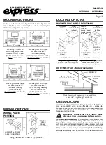
“MOUNTING OPTIONS”
•
“WIRING OPTIONS”
- Wiring Plate Position
•
“DUCTING OPTIONS”
- Blower Discharge Positions
- Ducting (Right-Angle Blower Discharge)
•
“USE AND CARE”
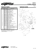
•
“SERVICE PARTS”
•
“WARRANTY”


