background image

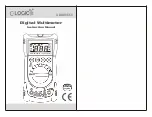
User's Manual 


2000A Auto Ranging 
True RMS Clamp + DMM 


MODEL 380926 


www.burntec.com

Summary of Contents for 380926

Page 1: ...User s Manual 2000A Auto Ranging True RMS Clamp DMM MODEL 380926 www burntec com ...

Page 2: ...death or serious injury CAUTION This indicates that a potentially hazardous condition which if not avoided could result in injury or damage to the meter Reply to request Safety Precautions 1 WARNING Improper use of this meter can cause damage shock injury or death Read and understand this user s manual before operating the meter 2 Make sure any covers or battery doors are properly closed and secur...

Page 3: ...ocated on the rear of the meter Symbols AC current or Voltage DC current or Voltage Continuity H Display hold REL Relative AUTO Auto range Diode Display Backlight Units mV V millivolt volt voltage Ω kΩ MΩ ohm kilohm megohm resistance percent duty cycle μA mA A microamps milliamps amps current Hz kHz hertz kilohertz frequency nF μF nanofarad microfarad capacitance www burntec com ...

Page 4: ...o select the range manually press the RANGE button before pressing DCA ZERO button 6 Read the measured value from the LCD display NOTE If the DCA zero button is used to zero the meter the clamp meter remains in the auto range mode If the REL button is used the clamp meter will be placed in the manual range mode Current Measurements using the Test Leads DC AC 1 Set the Function switch to the mA or ...

Page 5: ...tch to the Ω position 2 Press the FUNC key until the ohms symbol appears on LCD 3 Insert the black test lead to the COM input jack and the red test lead to the Ω input jack 4 Connect test leads to the device under test see diagram 5 Read the measured value from the LCD display Continuity Test 1 Set the Function switch to the position 2 Press the FUNC key until the Ω and symbols appear on the displ...

Page 6: ...k and the red test lead to the Hz input jack 4 Connect the tips of the test leads to the device to be measured see diagram 5 Read the frequency value in Hz on the LCD Duty Cycle Measurements Follow the steps as for Frequency measurements with the following exception Press the Hz key until the symbol appears on the display Capacitance Measurement 1 Set the Function switch to the position 2 Press th...

Page 7: ...ppear in the display Press HOLD again to return to normal operation Backlight Press and hold the Hold key for 2 seconds to activate the backlighting The backlight will automatically turn off to conserve energy after approx 12 seconds MAINTENANCE Battery Replacement When the low battery symbol appears on the LCD replace the meter s 9V battery 1 Remove power to the meter and remove test leads from m...

Page 8: ...tance 50µF 0 01µF 3 5d Accuracy stated after a relative REL zero performed Duty Cycle 1 to 99 0 1 1 5d Continuity Audible tone 10 ohms approximately Open circuit voltage 0 5V approximately Conductor Size 60mm 2 36 maximum Measurement parameters ACA DCA ACV DCV Resistance Diode Frequency Capacitance Duty Cycle Continuity Current Sensor Hall Effect Zero adjust Automatic except for DCA Push button Di...

Page 9: ...ts Function Maximum Rated Input Limits AC DC Current 500mA AC DC fused AC Voltage 1000 VAC DC DC Voltage 1000 VAC DC Resistance 400 VAC DC Frequency 1000 VAC DC Capacitance 400 VAC DC Duty Cycle 1000 VAC DC Diode Test 400 VAC DC www burntec com ...

Page 10: ...nsible for shipping charges freight insurance and proper packaging to prevent damage in transit This warranty does not apply to defects resulting from action of the user such as misuse improper wiring operation outside of specification improper maintenance or repair or unauthorized modification Extech specifically disclaims any implied warranties or merchantability or fitness for a specific purpos...

Reviews: