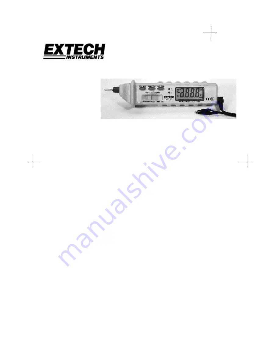
background image


Pen Multimeter


Model 381626


CAUTION:

 Read, understand and follow all  

Safety Rules and Operating Instructions in this 
 manual before using this product. 


Summary of Contents for 381626

Page 1: ...Pen Multimeter Model 381626 CAUTION Read understand and follow all Safety Rules and Operating Instructions in this manual before using this product ...

Page 2: ...vice if you are not qualified to do so EXTECH INSTRUMENTS CORPORATION warrants this instrument to be free of defects in parts and workmanship for one year from date of shipment If it should become necessary to return the instrument for service during or beyond the warranty period contact the Customer Service Department at 781 890 7440 for authorization A Return Authorization RA number must be issu...

Page 3: ...esponse DC Current 30 300mA 10µA 1 5 reading 3 digits 40Hz to 400Hz AC Current 30 300mA 10µA 2 0 reading 5 digits Average responding Resistance 300 3k 30k 300kΩ 3MΩ 30MΩ 0 1 ohms 1 5 reading 5 digits 2 0 reading 8 digits 3 0 reading 10 digits Overload Protection 250VAC rms Open ckt V 0 6V 1 2V Continuity Buzzer sounds for resistance less than 20 ohms approximately Logic 1V Logic low 1V to 2V Indet...

Page 4: ... voltages 3 DO NOT measure voltage above 500V DC or AC rms 4 ALWAYS turn off the power and disconnect the test leads before replacing the fuse or battery FUNCTIONAL DESCRIPTION 1 Data Hold Button 2 Range Hold Button 3 DC AC Button 4 Function Switch 5 Green LED 6 Red LED 7 Common Terminal 8 Positive Test Probe 9 Battery Fuse Door 10 LCD Display Bargraph 11 Function Switch Settings Switch Button V Ω...

Page 5: ...it will be canceled automatically if the Function switch is changed to another position OPERATION CAUTION This meter is a precision electronic instrument To avoid damaging the unit observe all safety statements contained in this manual DC or AC Voltage Measurement 1 Connect the black test lead to the COM jack 2 Set the Function Switch to the V position and select AC or DC 3 Connect the positive te...

Page 6: ... test probe is Diode Test 1 Connect the black test lead to the COM jack 2 Set the Function Switch to the position and select with Button 3 3 Connect the positive test probe and the black test lead across the diode under test If the positive test probe is placed on the anode of the diode the display will indicate the approximate forward voltage drop of the diode Logic Test 1 Connect the black test ...

Page 7: ...eplacement NOTE Do not operate the instrument or connect the test lead or probe to any circuit with the rear cover open 1 Remove the screw and open the battery door Replace the old batteries or the blown fuse with the same type Fuse 800mA 250V fast blow type Battery Two 1 5V AAA or UM 4 type ...

Reviews: