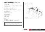
background image

WHAT YOU’LL NEED

Drill / Impact Driver x2
Socket Set & Shifter
Ladder x2
Mallet
Forklift / Crane / Scissor Lift *
Tape Measure
Stringline
Level
Marking Pencil
Stanley Knife

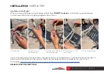
Warning read instructions carefully before use.

Recommended procedure to follow in this document. 

For safety reasons it is recommended that at least four  

persons set up any Crest Marquee.

Ensure area is free from any sharp objects & overhead objects.

www.extrememarquees.com.au     1300 850 832

Summary of Contents for FS 84 Series

Page 1: ...ine Level Marking Pencil Stanley Knife Warning read instructions carefully before use Recommended procedure to follow in this document For safety reasons it is recommended that at least four persons s...

Page 2: ...0 120 set 18 18 bolts and nuts M8 20 pc 3 3 Steel pins 25 500 pc 20 20 pin puller 1450 pc 1 1 pull ropes 16 20m pc 2 2 white roof cover 2980 6780 pc 3 3 white gable cover 1277 5920 pair 2 2 white side...

Page 3: ...extrememarquees com au 1300 850 832 3000 5815 6543 3 5905 3000 2960 125 3000 9000 70 250 125 125 135 8 6m x 9m FS SERIES 84 SETOUT PLAN 3000 5815 6543 3 5905 3000 2960 125 3000 9000 70 250 125 125 13...

Page 4: ...www extrememarquees com au 1300 850 832 6m x 9m FS SERIES 84 ELEVATION...

Page 5: ...6061 T6 13HW Cover Fabrics Material 850gsm White or Coloured PVC 950gsm Clear PVC Wall Fabrics Material 650gsm White PVC 850gsm Coloured PVC 950gsm Clear PVC All Materials are Waterproof UV Protectiv...

Page 6: ...s Brace B 8 Gable Eave Rail 9 Gable Support 10 Roof Purlin 11 Tension Bolt 12 Tension Bar 13 Connecting Rod 14 Mounting Fork Item Description 15 M10 x 70 Bolt 16 M10 x 100 Bolt 17 M10 x 120 Bolt Nut 1...

Page 7: ...itable for any surface Each Base Plate will need to have at least 200kg g Once constructed a safety inspection should be conducted on a regular basis 4 1 Dismantle Cautions h Mark and pack all compone...

Page 8: ...flat on the ground Refer to the Elevation Drawing and Parts List to confirm your method of construction for Step 2 FRAME TYPE A FRAME TYPE B STEP 2 A Assemble Corner Upright Corner Connector and Roof...

Page 9: ...and move into position Diagram note b 3m or 5m bays refer to elevation diagram STEP 5 A Connect the Reinforcing Beam Connect the two bays together using the Frame Reinforcing Beam and bolt together ST...

Page 10: ...e Support into the U type hook of Ridge Connector and fix with Bolt Fit the hook end of Gable Eave Rail on the D type hook of Gable Support Fit the other Gable Eave Rail to the D type hook on the Corn...

Page 11: ...t 2 Concrete Dynabolt Fix each Base Plate with Dynabolts 3 Weight Plate Ground Mounting suitable for any surface Each Base Plate will need to have at least 200kg 8 2 Weight Plate Fixing Fix the Corner...

Page 12: ...memarquees com au 1300 850 832 INSTALLATION HINTS TIPS Installation of Roof Fabric View of the outside and underside of Roof Panels REFER TO STEP 9 ON NEXT PAGES Outside of Roof Panels Underside of Ro...

Page 13: ...n a section of inter twined rope 3 Pull the start of the rope through the opening 4 Twirl the rope to close the opening 5 View of loop technique Connect the loop and pull the Roof Panels through the c...

Page 14: ...two installation ropes on the top of the frame as image 1 2 Layout the roof cover on ground as image 2 To keep the roof cover clean pls put one fabric or carpet or pallet on the bottom to hold the roo...

Page 15: ...pe MUST be on the underside of the roof panel 9 3 Insert the left right kedar side of roof cover into channel of roof beam Four people are required to completed this process Two people to evenly inser...

Page 16: ...au 1300 850 832 9 4 Continue to thread the roof kedar into the channel of the roof beam until the roof is fitted 9 5 Insert the curve tension bar into bottom sleeve of roof cover The bar is to be ins...

Page 17: ...Zip the centre of the left right gable cover together 10 4 Insert the curve tension bar into bottom sleeve of the gable cover IMPORTANT Curve tension bar must be put into the sleeve in smiley way up 1...

Page 18: ...urve tension bars and use fastener to tension gable cover 10 6 Finished gable cover STEP 11 Installing the Side Wall Fabric 11 1 Un zip separate the wall into two pieces left right IMPORTANT The sleev...

Page 19: ...www extrememarquees com au 1300 850 832 11 2 Insert slide the wall kedar into channel of eave purlin Tip gable side wall use the same installation method...

Page 20: ...com au 1300 850 832 11 3 Insert the left right kedar of the side wall into the channel of uprights Slide the wall kedar from top to bottom of the side uprights 11 4 Zip the centre of the left right s...

Page 21: ...1300 850 832 11 5 Insert the wall bar into the bottom sleeve of the wall using bolts tension the wall to the frame Tips Gable end wall bar s refer to image 1 and 2 Side panels wall bar s refer to imag...

Page 22: ...ble end and side panel lightly tension the bolt Tips The tension work can only be completed once the roof gable and side walls have been installed PLEASE NOTE The tension work can only be completed on...

Page 23: ...marquee is in use do not leave your marquee unattended Wind rating as per engineering certificate review weather conditions When the Marquee is in use and if part of the structure looks damaged or not...

Reviews: