background image

Extreme Networks, Inc.

3585 Monroe Street
Santa Clara, California 95051
(888) 257-3000
(408) 579-2800

http://www.extremenetworks.com


BlackDiamond X8 Series Switches Hardware 
Installation Guide

Published: February 2012
Part number: 120729-00 Rev. 01

Summary of Contents for BlackDiamond X8 Series

Page 1: ...Inc 3585 Monroe Street Santa Clara California 95051 888 257 3000 408 579 2800 http www extremenetworks com BlackDiamond X8 Series Switches Hardware Installation Guide Published February 2012 Part number 120729 00 Rev 01 ...

Page 2: ...rviceWatch Summit SummitStack Triumph Unified Access Architecture Unified Access RF Manager UniStack XNV the Extreme Networks logo the Alpine logo the BlackDiamond logo the Extreme Turbodrive logo the Summit logos and the Powered by ExtremeXOS logo are trademarks or registered trademarks of Extreme Networks Inc or its subsidiaries in the United States and or other countries sFlow is the property o...

Page 3: ...nagement Module 18 Management Module LEDs 20 I O Modules 21 BlackDiamond BDXA 10G48X I O Module 21 BlackDiamond BDXA 40G24X I O Module 22 BlackDiamond BDXA 40G12X I O Module 23 I O Module LEDs 24 Fabric Modules 25 Fan Trays 26 Chapter 3 Power Supplies for the BlackDiamond X8 Switch 27 Overview of the BlackDiamond X8 Series Power Supplies 27 AC Power Supply 28 LEDs 28 Fuse 29 Power Supply Cords 29 ...

Page 4: ...8 Series Chassis 47 Unpacking the Chassis 47 Pre Installation Requirements 50 Rack Mounting the Chassis 51 Grounding the Chassis 54 Installing Power Supplies 54 Connecting Power 58 Chapter 6 Installing BlackDiamond X8 Series Modules 59 Installation Order 59 Required Tools 59 Installing Fabric Modules 60 Installing Management Modules 64 Installing I O Modules 65 I O Module Blanks 67 Installing a Mo...

Page 5: ...ing Power Supply Units and Connecting Power 98 Selecting Power Supply Cords 99 Battery Replacement and Disposal 99 Fiber Optic Ports and Optical Safety 99 GBIC SFP Mini GBIC QSFP XENPAK and XFP Regulatory Compliance 100 Appendix B Technical Specifications 109 BlackDiamond X8 Switch 109 Modules for BlackDiamond X8 Switches 112 Power Supplies for BlackDiamond X8 Switches 113 Power Cord Requirements ...

Page 6: ...Contents BlackDiamond X8 Series Switches Hardware Installation Guide 6 ...

Page 7: ...idging concepts Routing concepts Simple Network Management Protocol SNMP Basic equipment installation procedures See the ExtremeXOS Concepts Guide and the ExtremeXOS Command Reference Guide for information about configuring the BlackDiamond X8 series switch NOTE If the information in an installation note or release note shipped with your Extreme Networks equipment differs from the information in t...

Page 8: ...rks products is available from the Extreme Networks website at the following location http www extremenetworks com go documentation You can download software concepts guides and reference guides hardware installation guides and other documents Under your product warranty or with a current support contract you can access software release notes and entitled software from the eSupport web pages at ht...

Page 9: ...ions To request an eSupport user name and password select the Request Web Login link on the eSupport home page at https esupport extremenetworks com You can see complete information about all of our services online at http www extremenetworks com solutions service solutions aspx ...

Page 10: ...Preface BlackDiamond X8 Series Switches Hardware Installation Guide 10 ...

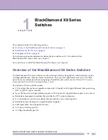
Page 11: ...PA R T About the BlackDiamond X8 Series Switches ...

Page 12: ......

Page 13: ... centers and high performance compute cluster installations They provide high density line rate 10 40 GbE ports For more information about configuring a BlackDiamond switch see the ExtremeXOS Concepts Guide and the ExtremeXOS Command Reference Guide The features of these switches include I O modules that are hot swappable and provide 10 Gigabit or 40 Gigabit Ethernet fiber ports using SFP or QSFP ...

Page 14: ...th slots for IO modules Two half width slots for management modules MMs Four vertical slots in the back behind fan trays for fabric modules FMs Eight bays in the front for redundant power supplies rear accessible power connections Five vertical fan trays at the back Two connectors for an ESD preventive wrist strap On the front panel between the management modules On the back panel at the top right...

Page 15: ...ESD preventive strap Figure 2 shows the back of the BlackDiamond X8 chassis Figure 2 Back of the BlackDiamond X8 Chassis The back of the BlackDiamond X8 chassis provides access to Eight AC power input connectors Five vertical fan trays Access to four fabric module slots behind the fan trays Connection point for ESD preventive strap Attachment point for optional chassis ground BDX_008 1 2 3 4 1 Gro...

Page 16: ... unit CPU of the switch You can plug an Ethernet cable directly from your laptop into the management port for direct access into the switch This access allows you to view and locally manage the switch configurations USB ports on the management module allow you to attach a single USB 2 0 flash drive Only a USB flash drive that is formatted using the file allocation table FAT file system is recogniz...

Page 17: ...ond X8 series switch include management modules I O modules and switch fabric modules Each module for the BlackDiamond X8 series switch consists of a printed circuit board mounted on a metal panel The module carrier also includes ejector injector levers and captive retaining screws on the module front panel Table 3 lists the module types and models available for the BlackDiamond X8 series switch T...

Page 18: ...management modules installed the management module in slot A becomes the primary If a switch is operating with one management module and a second management module is added to the switch after it has been powered up the added management module becomes the secondary Management modules that operate as secondary or backup management modules can be inserted and removed without disrupting network servi...

Page 19: ...nt Auxiliary AUX port For future development Management modules have the following LEDs see Table 4 Presence of system errors ERR System environmental status ENV Master backup status of the module MSTR General system status SYS General fan status FAN Fabric module status FM Figure 3 BDX MM1 Module BDX_011 1 2 3 4 1 LEDs 2 Management port and USB ports 3 Console port 4 Auxiliary port with LED ...

Page 20: ...up secondary MM Off Normal operation for diagnostics SYS System status Green blinking The system has booted and is operating normally Amber blinking Diagnostic tests are running on the module The LED resets if the diagnostics are terminated The LED returns to flashing amber if another diagnostic test is started Amber steady Diagnostic failure has occurred Off The switch is not receiving power FAN ...

Page 21: ...he module after it is inserted If you preconfigure a slot for a specific module type and then insert a different type of module the inserted module reverts to its default configuration See the ExtremeXOS Concepts Guide and the ExtremeXOS Command Reference Guide for feature specific information related to BlackDiamond X8 series modules BlackDiamond BDXA 10G48X I O Module The BDXA 10G48X I O module ...

Page 22: ...ailable The default mode for the ports is 40 Gbps operation To configure a port for 10 Gbps operation use the configure ports partition command Figure 5 BDXA 40G24X I O Module In the default configuration for the BDXA 40G24X module all ports Are added to the default VLAN as untagged Inherit the properties of the default VLAN for example protocol type and VLAN ID The BDXA 40G24X module has the foll...

Page 23: ...played as being available The default mode for the ports is 40 Gbps operation To configure a port for 10 Gbps operation use the configure ports partition command Figure 6 BDXA 40G12X I O Module In the default configuration for the BDXA 40G12X module all ports Are added to the default VLAN as untagged Inherit the properties of the default VLAN for example protocol type and VLAN ID The BDXA 40G12X m...

Page 24: ...I O Modules Type Label Function Color State Meaning Module STAT Module status Green blinking Normal operation Amber blinking Configuration error code version error diagnostic failure or other severe module error Off The module is not receiving power DIAG Module diagnostics Amber blinking Diagnostic tests are in progress Amber steady A diagnostic failure has occurred Off Normal operation Port Port ...

Page 25: ...full line rate for the BDXA 10G48X and BDXA 40G12X I O modules For the BDXA 40G24X I O module a BDXA FM20T switch fabric is required for full line rate on all ports The BDXA 40G24X I O module will not operate with a switch fabric composed of BDXA FM10T modules All the fabric modules in a BlackDiamond X8 switch must be the same type you cannot combine BDXA FM10T modules and BDXA FM20T modules Statu...

Page 26: ...he fabric module installed behind that fan tray Table 6 on page 25 and for the fan tray Table 7 Only the first four fan trays are associated with fabric modules Figure 8 Fan Trays in the BlackDiamond X8 Chassis Table 7 LEDs for the Fan Trays Label Function Color State Meaning Stat Green Fans are operating normally Amber blinking One or more fans are not operating properly Off No power Diag Amber s...

Page 27: ...f the BlackDiamond X8 Series Power Supplies The BlackDiamond X8 series switch is powered by AC power supplies that are installed at the top front of the chassis The power supply bay in the BlackDiamond X8 switch can accommodate up to eight AC power supplies The BlackDiamond X8 AC power supplies can operate from 110 VAC or 220 VAC and automatically adjust to the supply voltage With 220 V AC input t...

Page 28: ...g Power Supplies on page 54 LEDs The BlackDiamond X8 AC power supply has status LEDs on the front panel Table 8 describes the meanings of the LEDs Table 8 LEDs on the BlackDiamond X8 AC Power Supply LED Type and Color Power Supply Condition AC OK Green DC OK Green ALM Red No AC input power to any power supply Receiving standby output from backplane Off Off Off AC input power is present 48 V output...

Page 29: ...r supplies In the event of failure immediately return the defective Extreme Networks AC power supply for a complete replacement Power Supply Cords An AC power cord is not included with the BlackDiamond X8 AC power supply You can purchase AC power cords for use in the US and Canada from Extreme Networks or from your local supplier An AC power cord for use with the BlackDiamond X8 AC power supply mu...

Page 30: ...Chapter 3 Power Supplies for the BlackDiamond X8 Switch BlackDiamond X8 Series Switches Hardware Installation Guide 30 ...

Page 31: ...PA R T Hardware Installation ...

Page 32: ......

Page 33: ...y with communications protocols that are used on interconnected LANs and familiarity with basic installation procedures for networking equipment NOTE Before installing or removing any components of the system or before carrying out any maintenance procedures read the safety information in Appendix A of this guide Planning Your Site By carefully planning your site you can maximize the performance o...

Page 34: ...t Requirements Rack Specifications and Recommendations Operating Environment Requirements Verify that your site meets all environmental and safety requirements Virtually all areas of the United States are regulated by building codes and standards During the early planning stages of installing or modifying your LAN it is important that you develop a thorough understanding of the regulations that pe...

Page 35: ...sually indicated by the words UL Approved or UL Listed UL 333 Pfingsten Road Northbrook Illinois 60062 2096 USA http www ul com National Electrical Manufacturing Association NEMA USA only Organization of electrical product manufacturers Members develop consensus standards for cables wiring and electrical components NEMA 1300 N 17th Street Rosslyn Virginia 22209 USA http www nema org Electronics In...

Page 36: ...e met such as ambient temperature and humidity NOTE Extreme Networks recommends that you consult an electrical contractor for commercial building and wiring specifications Temperature Extreme Networks equipment generates a significant amount of heat It is essential that you provide a temperature controlled environment for both performance and safety Install the equipment only in a temperature and ...

Page 37: ... static electricity or electrostatic discharge ESD Take the following measures to ensure optimum system performance Remove materials that can cause electrostatic generation such as synthetic resins from the wiring closet Check the appropriateness of floor mats and flooring Connect metal chassis conduit and other metals to ground using dedicated grounding lines Use electrostatically safe equipment ...

Page 38: ...w these guidelines to ground equipment racks to the earth ground CAD weld appropriate wire terminals to building I beams or earth ground rods Use the appropriate chassis grounding wire for your system the correct size depends on the available input current to the power supply For AC systems using a 20A breaker per PSU SSI AC the chassis ground can be as small as 14 AWG The power cable ground shoul...

Page 39: ... rack provide a minimum of 24 inches 61 cm of space behind the mounted equipment Extra room on each side is optional Securing the Rack The rack should be attached to the wiring closet floor with 3 8 inch 9 5 mm lag screws or equivalent hardware The floor under the rack should be level within 3 16 inch 5 mm Use a floor leveling cement compound if necessary or bolt the racks to the floor as shown in...

Page 40: ... planning and installing a network Maintaining accurate records helps you to Relocate devices easily Make changes quickly Isolate faults in the distribution system Locate the opposite end of any cable Know the types of network devices that your cabling infrastructure can support Consider the following recommendations when setting up a cable labeling system suitable for your installation Identify c...

Page 41: ...m multimode fiber 500 550 meters 10 125 µm single mode fiber 5 000 meters 10 125 µm single mode fibera a Proprietary to Extreme Networks Connections between two Extreme Networks 1000BASE LX interfaces that use 10 125 μm single mode fiber can use a maximum distance of 10 000 meters 10 000 meters 1000BASE ZX 1550 nm optical window 10 125 µm single mode fiber 80 km 100BASE LX100 1550 nm optical windo...

Page 42: ...ency RF interference Discharge the RJ 45 Ethernet cable before plugging it into a port on the switch Use plenum rated cable when it is necessary for safety and fire rating requirements Consult your local building codes to determine when it is appropriate to use plenum rated cable or refer to IEC standard 850 Keep all ports and connectors free of dust CAUTION Unshielded twisted pair UTP cable can b...

Page 43: ...ere the cable connects to the I O module Figure 12 Bend Radius for Fiber Optic Cable Radio Frequency Interference If you use UTP cabling in an installation take precautions to avoid RF interference RF interference can cause degradation of signal quality and in an Ethernet network environment can cause excessive collisions loss of link status or other physical layer problems that can lead to poor p...

Page 44: ... connect each power supply to different independent power sources If a power source fails it will affect only the power supply to which it is connected If all switch power supplies are connected to a single power source the entire switch is vulnerable to a power source failure In regions that are susceptible to electrical storms Extreme Networks recommends that you plug your system into a surge su...

Page 45: ... a switch to prevent outages sags surges and bad harmonics from adversely affecting the performance of the device A UPS traditionally can perform the following functions Absorb relatively small power surges Smooth out noisy power sources Continue to provide power to equipment during line sags Provide power for some time after a blackout has occurred In addition some UPS or UPS plus software combin...

Page 46: ...requirements for your UPS we recommend that you add 30 to the total UPS Transition Time Transition time is the time that is necessary for the UPS to transfer from utility power to full load battery power For Extreme Networks products a transition time of less than 20 milliseconds is required for optimum performance Applicable Industry Standards For more information see the following ANSI TIA EIA s...

Page 47: ...allow you to install the chassis in a mid mount position This chapter includes the following sections Unpacking the Chassis on page 47 Pre Installation Requirements on page 50 Rack Mounting the Chassis on page 51 Grounding the Chassis on page 54 Installing Power Supplies on page 54 Connecting Power on page 58 Unpacking the Chassis CAUTION An unpopulated BlackDiamond X8 chassis weighs approximately...

Page 48: ...lustrations printed on the BlackDiamond X8 shipping container and unpack the chassis and accessories as follows 1 Cut the straps around the box Figure 13 Figure 13 Unstrapping the Box 2 Slide the box up and off the chassis and interior packing foam Figure 14 Remove the inside corner braces Figure 14 Removing the Box BDX_001 BDX_002 ...

Page 49: ... packing foam Pull apart the keyed corner of the lower packing foam and remove the lower packing foam from around the chassis Figure 15 Figure 15 Removing the Accessories and Foam 5 On each side remove the restraining bolts from the shipping brackets at the front and middle of the chassis Figure 16 Figure 16 Unbolting the Chassis 6 Open the accessory box and locate the four lifting handles BDX_003...

Page 50: ...etworks Verify that the following items are included in the shipping carton BlackDiamond X8 chassis with installed front shipping cover and MM slot cover Power cord retainer Two 19 inch support brackets Pre Installation Requirements In addition to the support brackets that are shipped with the chassis you need the following tools and equipment to install a BlackDiamond X8 chassis Mid mount bracket...

Page 51: ... install it Rack Mounting the Chassis NOTE The chassis provides three possible locations on each side for the mid mount brackets labeled A B and C When you attach the brackets make sure you use the same position on each side To install the chassis in a rack 1 Attach mid mount brackets to the sides of the chassis a On each side of the chassis align a mid mount brackets with its mounting holes on th...

Page 52: ...ion Figure 19 Screws are not provided To provide wider support for the chassis as you install it you can attach the second support bracket on the other side of the rack post Figure 19 Attaching the Support Bracket 4 If necessary attach the lifting handles to each side of the chassis 5 From the front of the rack lift the back of the empty BlackDiamond X8 chassis onto the support bracket 6 Slowly gu...

Page 53: ...s to the equipment rack using six rack mounting screws Screws are not provided Be sure that the screws are secure Refer to Figure 20 for the screw locations Figure 20 Securing the Chassis to the Rack After the chassis is secured to the equipment rack ground the chassis as described in the next section BDX_014 ...

Page 54: ...ssis Figure 21 Figure 21 Grounding Pad on the Chassis 2 Strip 0 5 inch 1 2 cm of insulation from the stranded copper wire cable 3 Insert the stripped wire into the cable lug 4 Crimp the lug securely onto the cable 5 Insert the screws through the lug and into the grounding pad on the back of the chassis 6 Connect the other end of the wire to a known reliable earth ground point at your site After th...

Page 55: ...chassis c Lift the cover panel away from the chassis Figure 22 Removing the Power Supply Ventilation Cover 2 Identify the power supply bay where you will install the power supply Power supply bays are numbered from 1A to 8B Figure 23 To establish an N N redundant power configuration install power supplies in both the upper and lower rows Figure 23 Power Supply Bay Numbering on the Chassis 3 On the...

Page 56: ... through 5 to install other power supplies as required by your system configuration 7 Replace the power supply ventilation cover as follows a Set the lower edge of the cover in place so that the tabs on the edge fit into the matching slots in the chassis frame Figure 25 b Rotate the top of the cover into place against the front of the chassis frame c Align and tighten the retaining screws CAUTION ...

Page 57: ...Installing Power Supplies BlackDiamond X8 Series Switches Hardware Installation Guide 57 Figure 25 Installing the Power Supply Ventilation Cover BDX_019 ...

Page 58: ...ch installed power supply Power input sockets are numbered from 1A to 8B from left to right as you face the chassis back Figure 26 Figure 26 Numbers for Power Connectors 2 After all the power cords have been connected set the power cord retainer over the power cord connectors and against the back of the chassis Figure 27 3 Align and tighten the captive retaining screws on the power cord retainer F...

Page 59: ...65 I O Module Blanks on page 67 Initial Management Access on page 69 Installation Order For an initial system installation the recommended order for populating the chassis is 1 Install all fabric modules FMs 2 Install all management modules MMs 3 Install I O modules Required Tools You need the following tools and equipment to install modules in a BlackDiamond X8 chassis ESD preventive wrist strap ...

Page 60: ... only three fabric modules use slots 1 through 3 Install all the fabric modules before you install I O modules To install fabric modules 1 Attach the ESD preventive wrist strap to your bare wrist If it is not already connected connect the metal end to the receptacle at the right of the power input connectors 2 Remove the fan tray from each location where you will install a fabric module Figure 28 ...

Page 61: ...e screws on the insertion extraction levers and open the levers Figure 29 Figure 29 Installing a Fabric Module b Align the circuit board with the guides at the top and bottom of the chassis and slide the module into the chassis c When the levers start to engage push them toward the module to seat the module in the chassis BDX_021 ...

Page 62: ...ules BlackDiamond X8 Series Switches Hardware Installation Guide 62 d Align and tighten the retaining screws to fasten the module in place Figure 30 Figure 30 Securing a Fabric Module 4 Repeat these steps to install additional fabric modules BDX_023 ...

Page 63: ...8 Series Switches Hardware Installation Guide 63 5 Re install the removed fan trays a Set each fan tray into the chassis and push it firmly into place Figure 31 b Align and tighten the retaining screws Figure 31 Installing a Fan Tray BDX_025 ...

Page 64: ...r from the unoccupied slot 3 Remove the module from the antistatic packaging CAUTION To prevent ESD damage hold the module by the metal rail and front panel only Never touch the components on the PCB or the pins on any of the connectors 4 Verify that the injector ejector handle is in the open position Figure 32 Keep the injector ejector handle in the open position as you slide the module into the ...

Page 65: ... compliance Individual I O module blanks are purchased separately from the chassis To install I O modules 1 Remove the shipping cover from the I O module slots The shipping cover maintains the mechanical stability of the chassis during shipping Keep the shipping cover and store it with the other chassis shipping materials in case you need to move the chassis or return it to Extreme Networks 2 Atta...

Page 66: ... the module into the chassis slot NOTE If the injector ejector handles are in the latched position they prevent the module from sliding all the way into the slot Figure 34 Installing an I O Module 5 Carefully slide the module into the slot until the injector ejector handles engage the edges of the chassis and begin to rotate toward the center of the module 6 Push the handles toward each other to s...

Page 67: ...to Place I O Module Blanks BlackDiamond X8 switches are shipped with a reinforcement shipping cover installed over all the I O module slots After you have installed all the I O modules for your system configuration you must install module blanks in all remaining unoccupied slots CAUTION All unoccupied slots in a BlackDiamond X8 series switch must have module blanks correctly installed to ensure co...

Page 68: ...confirm that the gaskets are not damaged 2 Align the module blank with the card guides for the open slot on the chassis see Figure 36 Figure 36 Installing a Module Blank 3 Use a 2 Phillips screwdriver to tighten the captive screws at each end of the module blank NOTE Tighten the screws of each installed module blank before inserting additional modules or blanks Otherwise you might unseat modules o...

Page 69: ...our local supplier or you can make your own To ensure the electromagnetic compatibility of the unit use only shielded serial cables For information about the DB 9 console plug connector see Connector Pinouts on page 114 Logging In for the First Time To log in and manually configure the IP settings 1 Connect a terminal or PC with terminal emulation software to the management module in the BlackDiam...

Page 70: ... specific system name see the ExtremeXOS Concepts Guide 6 Assign an IP address and subnetwork mask for VLAN default by typing configure vlan default ipaddress 123 45 67 8 255 255 255 0 Your changes take effect immediately 7 Save your configuration changes so that they will be in effect after the next system reboot by typing save The configuration is saved to the configuration database of the manag...

Page 71: ...PA R T Maintenance Procedures ...

Page 72: ......

Page 73: ...ides instructions for maintenance procedures for the BlackDiamond X8 switch and includes the following sections Replacing a Power Supply on page 74 Replacing a Fan Tray on page 76 Replacing a Fabric Module on page 78 Replacing a Management Module on page 82 Replacing an I O Module on page 86 Packing the Chassis for Shipping on page 89 ...

Page 74: ...ws at the top corners of the cover panel b Pull outward on the retaining screws to tilt the cover panel away from the front of the chassis c Lift the cover panel away from the chassis Figure 37 Removing the Power Supply Ventilation Cover 2 Push the release button for the inserter extractor lever on the front of the power supply 3 Rotate the inserter extractor lever to the right to unseat the power...

Page 75: ...front of the replacement power supply push the release button for the insertion ejector lever 6 Slide the power supply into the chassis until the lever starts to engage Figure 39 Figure 39 Installing a Power Supply 7 Rotate the lever toward the front of the power supply to fully seat the power supply in the chassis BDX_037 BDX_018 ...

Page 76: ...s Figure 40 Installing the Power Supply Ventilation Cover CAUTION Do not operate the BlackDiamond X8 switch without the power supply ventilation cover in place This cover is required to maintain proper EMI levels for the switch Replacing a Fan Tray You need a 2 Phillips screwdriver to replace a fan tray You can replace a fan tray without powering down the switch To replace a fan tray 1 Completely ...

Page 77: ...stallation Guide 77 Figure 41 Removing a Fan Tray 3 Holding the replacement fan tray with both handles align it with the opening and slide it straight into the chassis Figure 42 4 Align and tighten the retaining screws Figure 42 Installing a Fan Tray BDX_020 BDX_025 ...

Page 78: ...c module You can replace a fabric module without powering down the switch To replace a fabric module 1 Attach the ESD preventive wrist strap to your bare wrist If it is not already connected connect the metal end to the receptacle at the right of the power input connectors 2 Remove the fan tray in front of the faulty fabric module a Loosen the captive retaining screws at the top and bottom of the ...

Page 79: ...Guide 79 3 Remove the fabric module a Loosen the retaining screw on each inserter extractor lever on the fabric module Figure 44 b Simultaneously rotate both levers toward the ends of the module to unseat the internal connectors Figure 44 Figure 44 Unseating a Fabric Module BDX_024 ...

Page 80: ... and set it aside on an anti static surface Figure 45 Removing a Fabric Module 4 Install the replacement fabric module a Remove the module from the antistatic packaging a Loosen the screws on the insertion extraction levers and open the levers b Align the circuit board with the guides at the top and bottom of the chassis and slide the module into the chassis Figure 46 BDX_022 ...

Page 81: ...allation Guide 81 Figure 46 Installing a Fabric Module c When the levers start to engage push them toward the module to seat the module in the chassis d Align and tighten the retaining screws to fasten the module in place Figure 47 Securing a Fabric Module BDX_021 BDX_023 ...

Page 82: ... tools and equipment to replace a BlackDiamond X8 series management module ESD preventive wrist strap 2 Phillips screwdriver Module blank panel if you are not replacing the module You can replace a management module without powering down the switch Removing a Management Module To remove a management module 1 Attach the ESD preventive wrist strap to your bare wrist If it is not already connected co...

Page 83: ...ndle and rotate the handle to the right away from the module to unseat the module from the internal connectors Figure 50 Figure 50 Removing a Management Module 5 Slide the module out of the chassis slot Immediately place the module into an anti static bag to protect it from potential ESD damage The bag will also prevent dust from collecting on the module connectors 6 If you are not going to instal...

Page 84: ...dle is in the open position Figure 51 Keep the injector ejector handle in the open position as you slide the module into the chassis slot 3 Carefully slide the module into the slot until the injector ejector handle engages the edge of the chassis and begins to rotate toward the module 4 Use the lever to fully seat the internal module connectors Figure 51 Installing a Management Module 5 Use a 2 Ph...

Page 85: ... management module is not installed in a slot you must install a blank cover over the slot to maintain proper EMI levels and ventilation to ensure conformance to FCC requirements as well as to maintain adequate airflow through the switch To install a management module blank 1 Set the blank in place over the open slot 2 Align and tighten the captive retaining screws BDX_016 ...

Page 86: ... ESD preventive wrist strap to your bare wrist If it is not already connected connect the metal end to the receptacle between the management module slots 2 Disconnect network cables from the front of the module 3 On each injector ejector lever turn the captive screw counter clockwise until the yellow band around the screw head of is completely visible Figure 53 Figure 53 Unlocking a Module 4 Squee...

Page 87: ...stall an I O module 1 Remove the replacement module from the antistatic packaging CAUTION To prevent ESD damage hold the module by the metal rail and front panel only Never touch the components on the circuit board or the pins on any of the connectors 2 Verify that the module injector ejector handles are open Keep the injector ejector handles in the open position as you slide the module into the c...

Page 88: ...avoid over torquing and stripping the screw heads Figure 56 Locking the Module into Place Installing I O Module Blanks All unoccupied slots in a BlackDiamond X8 series switch must have blank front panels correctly installed to ensure conformance to FCC requirements as well as to maintain adequate airflow through the switch To install an I O module blank 1 Check the condition of the EMI gaskets alo...

Page 89: ...scribes how to pack the BlackDiamond X8 chassis for shipment back to Extreme Networks You need the following tools and materials to pack a BlackDiamond X8 series chassis Original shipping cover for the front module slots Lifting handles that were shipped with the chassis Original shipping box and packing materials Screwdriver for ground lug screws Four rack mounting screws for attaching the suppor...

Page 90: ...e slots Removing the Chassis from the Rack To remove the chassis from the rack 1 On the back of the chassis remove the screws from the ground lug to disconnect the ground wire from the chassis 2 Using four mounting screws attach the support brackets to the equipment rack immediately below the chassis 3 Remove the rack mounting screws that secure the chassis to the rack 4 Slowly guide the chassis o...

Page 91: ... chassis 1 At each corner attach a restraining bolt to the shipping bracket securing the BlackDiamond X8 chassis to the shipping pallet see Figure 59 Figure 59 Recrating the BlackDiamond X8 Chassis 2 Put the lower foam cushion around the base of the chassis and set the upper foam cap on top of the chassis Figure 60 Figure 60 Placing the Foam Cushioning Around the Chassis BDX_039 BDX_040 ...

Page 92: ... Guide 92 3 Set a corner brace at each corner of the chassis and slide the shipping carton down over the chassis Figure 61 Figure 61 Placing the Shipping Carton over the Chassis 4 Secure the carton to the pallet using nylon strapping Figure 62 Figure 62 Shipping Carton with Nylon Straps BDX_041 BDX_042 ...

Page 93: ...PA R T Appendices ...

Page 94: ......

Page 95: ...al training and experience necessary to be aware of the hazards to which they are exposed in performing a task and are aware of measures to minimize the danger to themselves or other persons If you are in the USA install the system in accordance with the U S National Electrical Code NEC This appendix includes the following sections Considerations Before Installing on page 96 Maintenance Safety on ...

Page 96: ... chassis cover is not designed to support weight Maintenance Safety When you perform maintenance procedures on Extreme Networks equipment follow these recommendations Use only authorized accessories or components approved for use with this system Failure to follow these instructions may damage the equipment or violate required safety and EMC regulations This system contains no customer serviceable...

Page 97: ...long Cable runs between buildings are directly buried Cable runs between buildings are in an underground conduit where a continuous metallic cable shield or a continuous metallic conduit containing the cable is bonded to each building grounding electrode system CAUTION Failure to follow these requirements for cable routing conditions may expose the user to electrical shock and expose the unit to d...

Page 98: ... are certified for use within the country of use Do not attempt to modify AC power cords Make sure that the voltage and frequency of your power outlet match the system electrical ratings for the equipment The building and or power source must provide overload protection Use a surge suppressor line conditioner or uninterruptible power supply to protect the system from momentary increases or decreas...

Page 99: ... down the voltage to 240V AC from phase phase or that you make a connection to a P N PE power distribution where voltages do not exceed 240V AC All installations should confirm that the product is reliably grounded according to the country s local electrical codes Battery Replacement and Disposal Batteries included with Extreme products are encapsulated and must be replaced only by qualified Extre...

Page 100: ...in this document NOTE Extreme Networks optical modules are tested to work in all supported Extreme Networks switches We recommend that all customers use Extreme Networks optical modules in their Extreme Networks switches Extreme Networks assumes no liability for third party optical modules Although Extreme Networks does not block third party optical modules we cannot ensure that all third party op...

Page 101: ...und Feuchtigkeit werden kontrolliert und die maximale Raumtemperatur liegt nicht über 40 ºC Sauber und frei von in der Luft enthaltenen Stoffen die Elektrizität übertragen können Gut belüftet und fern von Wärmequellen inklusive direkter Sonneneinstrahlung Fern von Quellen für Erschütterungen oder mechanische Einwirkungen Getrennt von starken elektromagnetischen Feldern die von elektrischen Geräten...

Page 102: ...ährend eines Gewitters nicht an dem System und stecken Sie keine Kabel an oder ab Das Gerät muss geerdet werden Der Schutzleiter darf nicht manipuliert oder umgangen werden und das Gerät darf auf keinen Fall ohne einen entsprechend installierten Schutzleiter betrieben werden Sicherheit bei Wartungsarbeiten Befolgen Sie bei allen Wartungsarbeiten an Extreme Networks Geräten folgende Empfehlungen Ve...

Page 103: ...ein durchgehender metallischer Kabelschirm oder eine durchgehende Metallleitung die das Kabel umschließt an den Erdungselektrodensystemen der einzelnen Gebäude angeschlossen ist ACHTUNG Eine Missachtung dieser Bedingungen für die Kabelverlegung kann Nutzer der Gefahr eines elektrischen Stromschlages aussetzen und das Gerät so beschädigen dass es nicht mehr einwandfrei arbeitet WARNUNG Die Ethernet...

Page 104: ...r den Metallgegenstand mit den Anschlüssen verschweißen kann Wenn das Netz bei angeschlossener Netzversorgung angeschlossen oder getrennt wird kann ein elektrischer Lichtbogen entstehen Dies kann bei Installationen in Gefahrenbereichen zu einer Explosion führen Achten Sie unbedingt darauf dass das Gerät nicht mit der Netzversorgung verbunden ist Achten Sie bei der Installation oder beim Austausch ...

Page 105: ... geschultes und qualifiziertes Wartungspersonal Zugang zu den Geräten hat Ein zugangsbeschränkter Bereich kann beispielsweise nur mithilfe eines Spezialwerkzeugs Schloss und Schlüssel oder einer anderen Sicherheitsvorrichtung geöffnet werden HINWEIS Da die Gebäudevorschriften in aller Welt unterschiedlich sind empfiehlt Extreme Networks dringend sich bezüglich der korrekten Erdung und Spannungsver...

Page 106: ...nd Solche Geräte sind nicht nur Gigabit Interface Konverter GBICs steckbare Kleinformfaktormodule SFP oder Mini GBICs QSFP Module XENPAK Sendeempfänger und laseroptische XFP Module WARNUNG Laseroptische Module können bei längerem Gebrauch sehr heiß werden Seien Sie beim Ausbau eines laseroptischen Moduls aus dem Modul oder der Optionskarte äußerst vorsichtig Wenn das laseroptische Modul zum Anfass...

Page 107: ... erfüllen folgende gesetzliche Vorschriften Laserprodukt der Klasse 1 oder Klasse 1M EN60825 1 2007 2 Ausgabe oder später Europäische Norm FCC 21 CFR Kapitel 1 Paragraph J in Übereinstimmung mit FDA und CDRH Bestimmungen Anwendung des CE Zeichens gemäß der EMV Richtlinie 2004 108 EEC und der Niederspannungsrichtlinie 2006 95 EC UL und oder CSA geprüfte Komponente für Nordamerika 47 CFR Teil 15 Kla...

Page 108: ...Appendix A Safety Information BlackDiamond X8 Series Switches Hardware Installation Guide 108 ...

Page 109: ...cal Specifications Physical Characteristics BlackDiamond X8 chassis Height 25 inches 63 5 cm Width 18 inches 45 7 cm Depth 30 inches 76 2 cm Note Handles on the fan trays add 1 25 inches 3 2 cm to the depth of the chassis Weight empty 187 4 lb 85 kg Weight with 5 fan trays 218 4 lb 99 1 kg Weight fully loaded 420 6 lb 190 6 kg BlackDiamond X8 fan tray Height 24 inches 60 9 cm Width 4 inches 10 1 c...

Page 110: ...4 Ed 2 0 2010 Transient Burst 2kV Criteria A IEC EN 61000 4 5 Ed 2 0 2010 Surge 1 2kV Criteria A IEC EN 61000 4 6 Ed 3 0 2008 Conducted Immunity 0 15 80MHz 10V rms unmod Criteria A IEC EN 61000 4 11 Ed 2 0 2004 Power Dips Interruptions 30 25 periods Criteria C 2004 108 EC EMC Directive International CISPR 22 2005 A1 2005 Class A International Emissions CISPR 24 1997_A1 2001 A2 2002 International I...

Page 111: ... to 70 C 40 F to 158 F Storage and transportation humidity 10 to 93 relative humidity non condensing Packaged shock half sine 50 kg 180 m s2 10 g 6 ms 600 shocks modules 50 kg 100 m s2 6 g 11 ms 600 shocks chassis Packaged random vibration 5 to 20 Hz 1 0 ASD w 3 dB oct from 20 to 200 Hz 14 drops minimum on sides corners 39 5 22 lb 10 kg modules 11 8 110 lb 50 kg chassis Acoustic Sound Sound pressu...

Page 112: ...kg Packaged weight 18 85 lb 8 57 kg Power 510 W Heat Dissipation 1740 BTU BDXA 40G12X Weight 11 0 lb 5 0 kg Packaged weight 14 lb 6 3 kg Power 265 W Heat Dissipation 904 BTU Module blank Weight 4 85 lb 2 20 kg Management Module Dimensions 3 inches high by 8 inches wide by 18 inches deep 7 6 cm x 20 3 cm x 45 7 cm BDXA MM1 Weight 5 5 lb 2 5 kg Packaged weight 7 90 lb 3 59 kg Power 150 W Heat Dissip...

Page 113: ...supplies Full configuration 8 power supplies Physical characteristics Height 1 5 inches 3 8 cm Width 4 2 inches 10 6 cm Depth 14 5 inches 36 8 cm Weight 5 3 lb 2 4 kg Packaged weight 6 15 lb 2 80 kg Input Rated inputs Low range 100 to 120 V 60 50 Hz 13 A maximum each power supply High range 200 to 240 V 60 50 Hz 13 A maximum each power supply Input ranges Low range 90 to 132 V 47 to 63 Hz 15 4 A H...

Page 114: ... Direction CTS clear to send 1 In DTR data carrier detect 2 Out TXD transmit data 3 Out GND ground 4 GND ground 5 RXD receive data 6 In DSR data set ready 7 In RTS request to send 8 Out Table 16 Pinouts for an RJ 45 to DB 9 Adapter Signal RJ 45 Pin DB 9 Pin CTS clear to send 1 8 DTR data carrier detect 2 6 TXD transmit data 3 2 GND ground 4 5 GND ground 5 5 RXD receive data 6 3 DSR data set ready ...

Page 115: ... reasonable protection against harmful interference when the equipment is operated in a commercial environment This equipment generates uses and can radiate radio frequency energy and if not installed and used in accordance with the instruction manual may cause harmful interference to radio communications Operation of this equipment in a residential area is likely to cause harmful interference in ...

Page 116: ...n which case the user may be required to take appropriate measures WARNING 警告使用者 這是甲類的資訊產品 在居住的環境中使用時 可能會造成射頻干擾 在這種情況下 使用者會被要求採取某些適當的對策 WARNING Japan VCCI Class A This is a Class A product based on the standard of the VCCI Council If this equipment is used in a domestic environment radio interference may occur in which case the user may be required to take corrective actions 警告 此为A级产品 在生活环境中 该产品可能...

Page 117: ...us fiber optic 43 UTP 42 category 5 42 fiber optic 43 installing 42 slack 42 types and distances 41 cable labeling 40 cabling standards ANSI 46 BICSI 40 capacity switch fabric 25 category 5 cable 42 chassis installing 51 packing for shipping 89 unpacking 48 commercial building standards 46 compatibility switch fabric 25 components installing fabric modules 60 I O modules 65 management modules 64 m...

Page 118: ... 112 types 17 identification records cable 40 IEEE 802 3 media access standards 110 industry standards 46 initial switch login 69 installation chassis 51 fabric modules 60 fan tray 76 I O modules 65 management modules 64 module blank 68 88 power supply 55 IP settings configuring 69 L labeling system for cables 40 LEDs AC power supply 28 fan tray 26 I O modules 24 management module 20 switch fabric...

Page 119: ...slack cable 42 space requirements rack 39 specifications AC power supply 113 BlackDiamond X8 switch 109 modules 112 standards cabling 40 46 commercial building 46 grounding 46 rack 37 storage conditions 111 support bracket 52 switch configuration saving 18 switch fabric capacity 25 T technical specifications AC power supply 113 BlackDiamond X8 switch 109 modules 112 telecom standards 110 temperatu...

Page 120: ...x BlackDiamond X8 Series Switches Hardware Installation Guide 120 wiring closet airflow requirements 37 electrostatic discharge 37 floor coverings 36 grounding 36 humidity 37 rack securing 39 temperature 36 ...

Reviews: