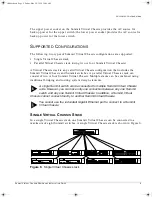
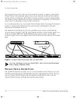
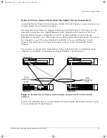
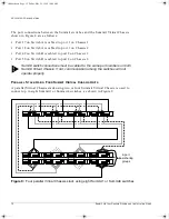
background image

Extreme Networks, Inc.

10460 Bandley Drive

Cupertino, California 95014

(888) 257-3000

http://www.extremenetworks.com

Summit Virtual Chassis 
Design and Installation 
Guide

Published: June 1998

Part No: 120031-00 rev. 01

virtchas.book  Page i  Friday, May 29, 1998  10:08 AM

Summary of Contents for Summit Virtual

Page 1: ...Bandley Drive Cupertino California 95014 888 257 3000 http www extremenetworks com Summit Virtual Chassis Design and Installation Guide Published June 1998 Part No 120031 00 rev 01 virtchas book Page i Friday May 29 1998 10 08 AM ...

Page 2: ...such as translation transformation or adaptation without permission from Extreme Networks Inc Extreme Networks ExtremeWare Summit SummitLink Virtual Chassis and the Extreme Networks logo are trademarks of Extreme Networks All other brand and product names are registered trademarks or trademarks of their respective holders virtchas book Page ii Friday May 29 1998 10 08 AM ...

Page 3: ...hes into one cohesive system The Summit Virtual Chassis comes with eight SummitLink backplane channels SUMMARY OF FEATURES Features of the Summit Virtual Chassis include the following Increased port density Policy based Quality of Service QoS Load sharing links Extensive fault tolerant capabilities Redundant power supplies Hot swappable switches Hot swappable Virtual Chassis Environmental sensors ...

Page 4: ...can define QoS traffic groups based on the following Internet Protocol IP destination address Virtual LAN VLAN including IP subnet or protocol Media Access Control MAC destination address Physical source port 802 1p prioritization ExtremeWare software running on the Summit switch maps the QoS profiles into queues on each port of the switch When up to eight Summit switches are connected to a Summit...

Page 5: ...of parallel paths Figure 2 Two port load sharing links with the Summit Virtual Chassis Using load sharing links the Summit Virtual Chassis distributes traffic to and from each Summit switch on any of the parallel connected paths This results in faster data throughput among the switches connected to the Summit Virtual Chassis Switch 1 4 port load sharing groups Switch 8 Switch 1 2 port load sharing...

Page 6: ...ides power to the Summit Virtual Chassis Combined the two power supplies provide load balancing to increase the longevity of each supply and deliver uninterrupted service in the event of a failure In addition to the two internal power supplies the Summit Virtual Chassis comes with dual external redundant power supplies RPS that deliver power for up to two Summit switches in the stack DC cables are...

Page 7: ...m LED on a Summit Virtual Chassis indicates a failure the Summit Virtual Chassis can be disconnected removed from the stack and replaced while remaining transparent to all users All traffic continues to pass through the operational Summit Virtual Chassis while the failed unit is replaced ENVIRONMENTAL SENSORS The Summit Virtual Chassis is equipped with sensors that monitor the internal temperature...

Page 8: ...us LEDs Color Indicates PS1 Green Off Power supply 1 of the Summit Virtual Chassis is operating The Summit Virtual Chassis is indicating a power supply failure RPS1 Green The first redundant power supply RPS of the Summit Virtual Chassis is powering a Summit switch PS2 Green Off Power supply 2 of the Summit Virtual Chassis is operating The Summit Virtual Chassis is indicating a power supply failur...

Page 9: ... Summit switch connected to the Summit Virtual Chassis using RPS port A SummitLink Port Status LEDs Link Green Yellow Off Link is present Link error No link or either the Summit Virtual Chassis or the Summit switch attached to this port is powered off TX Activity Yellow Off Frames are being transmitted on this port No transmit activity detected on this port RX Activity Yellow Off Frames are being ...

Page 10: ... must plug the Summit switch AC power cord into a different circuit breaker than the circuit breaker to which the Summit Virtual Chassis AC power socket is connected REDUNDANT POWER SUPPLY PORTS The Summit Virtual Chassis has two RPS ports Each port connects to a different Summit switch Figure 5 shows the rear view of a rack that has one Summit switch mounted above the Summit Virtual Chassis and o...

Page 11: ... Virtual Chassis stack can consist of two or four Summit Virtual Chassis Multiple stacks can be combined using traditional bridging and routing system design elements A single Summit switch can be connected to multiple Summit Virtual Chassis units However you can have only one connection between any one Summit switch and any one Summit Virtual Chassis In addition a Summit Virtual Chassis cannot co...

Page 12: ...it Virtual Chassis can provide redundant power for two of the Summit switches shown in Figure 6 For the other Summit switches to have backup power you must use a Summit RPS The Summit RPS provides power to up to two Summit switches Figure 7 shows the single Virtual Chassis stack with the addition of a Summit RPS Figure 7 Single Virtual Chassis stack with a Summit RPS For more information on using ...

Page 13: ...rts on one of the Summit Virtual Chassis Port 18 on the Summit2 or port 50 on the Summit48 is cabled to the second Summit Virtual Chassis You must use the same port number on each of the two Summit Virtual Chassis For example in Figure 8 two Summit2 switches labeled Switch A and Switch B are cabled to two Summit Virtual Chassis labeled Chassis 1 and Chassis 2 Figure 8 Parallel Virtual Chassis stac...

Page 14: ...h B is cabled to port 2 on Chassis 2 Summit switch connections must be cabled to the same port numbers on both Summit Virtual Chassis If not communication among the switches will not operate properly PARALLEL STACK USING FOUR SUMMIT VIRTUAL CHASSIS UNITS A parallel Virtual Chassis stack using two or four Summit Virtual Chassis is used to connect up to eight Summit1 or Summit4 switches as shown in ...

Page 15: ...ions between the Summit1 switches and the four Summit Virtual Chassis are as follows Port 4 on Switch A is cabled to port 2 on Chassis 1 Port 5 on Switch A is cabled to port 2 on Chassis 2 Port 6 on Switch A is cabled to port 2 on Chassis 3 Port 7 on Switch A is cabled to port 2 on Chassis 4 Port 4 on Switch B is cabled to port 6 on Chassis 1 Port 5 on Switch B is cabled to port 6 on Chassis 2 Por...

Page 16: ...g rules port redundancy rules and so on The second method uses a Summit switch that is a member of both Virtual Chassis stacks Using this method you must adhere to the requirements of both stacks when connecting the switch For example a single port is used for connecting to a single Virtual Chassis stack two ports are used for connecting to a parallel Virtual Chassis stack that has two Summit Virt...

Page 17: ...LLEL VIRTUAL CHASSIS STACK The Summit3 switch has one active Gigabit Ethernet port Therefore it can have one active connection to a Summit Virtual Chassis Figure 12 shows how you would add a Summit3 to the example used in the parallel Virtual Chassis example using Summit2 switches shown previously in Figure 8 Table 2 Summit Switch Support for Virtual Chassis Stacks Single Virtual Chassis Stack Par...

Page 18: ... on Switch A is cabled to port 1 on Chassis 1 Port 18 on Switch A is cabled to port 1 on Chassis 2 Port 49 on Switch B is cabled to port 2 on Chassis 1 Port 50 on Switch B is cabled to port 2 on Chassis 2 Port 25 on Switch C is cabled to port 3 on Chassis 1 Nothing is cabled to port 3 on Chassis 2 Connecting a device to port 3 on Chassis 2 can result in frames being delivered to the wrong switch O...

Page 19: ...Summit Virtual Chassis are detailed in the Summit Installation and User Guide These include the following You must configure the Summit switch port s prior to connecting the switch to the Summit Virtual Chassis Each connected port must be configured as a SummitLink port If you are using a parallel Virtual Chassis stack you must configure load sharing on the Summit switch after the ports are design...

Page 20: ...e RPS DC cable must be connected to the Summit switch prior to connecting the AC power cord to the Summit Virtual Chassis b Tighten the screws connecting both sides of the RPS cable Ensure that the cable is secured and is making good contact prior to turning on the Summit Virtual Chassis c Connect an AC power cord to each power socket d Plug the power cords into properly grounded AC outlets When d...

Page 21: ...densing Regulatory Compliance EN55022 Class B FCC part 15 Class A CSA C108 8 M1983 A VCCI Class 2 EN50082 1 IEC 801 Parts 2 4 EN61000 3 2 EN61000 4 3 EN61000 4 5 EN61000 4 6 EN61000 4 11 UL 1950 3rd Edition CSA 22 2 950 EN60950 1992 A3 1995 TUV GS Rheinland CE Mark Heat Dissipation 236W maximum 682 4 BTU hr maximum Power supply AC Line Frequency Input Voltage Options Current Rating 47Hz to 63Hz 90...

Page 22: ...20 SUMMIT VIRTUAL CHASSIS DESIGN AND INSTALLATION GUIDE TECHNICAL SPECIFICATIONS virtchas book Page 20 Friday May 29 1998 10 08 AM ...

Reviews: