background image

SMX System

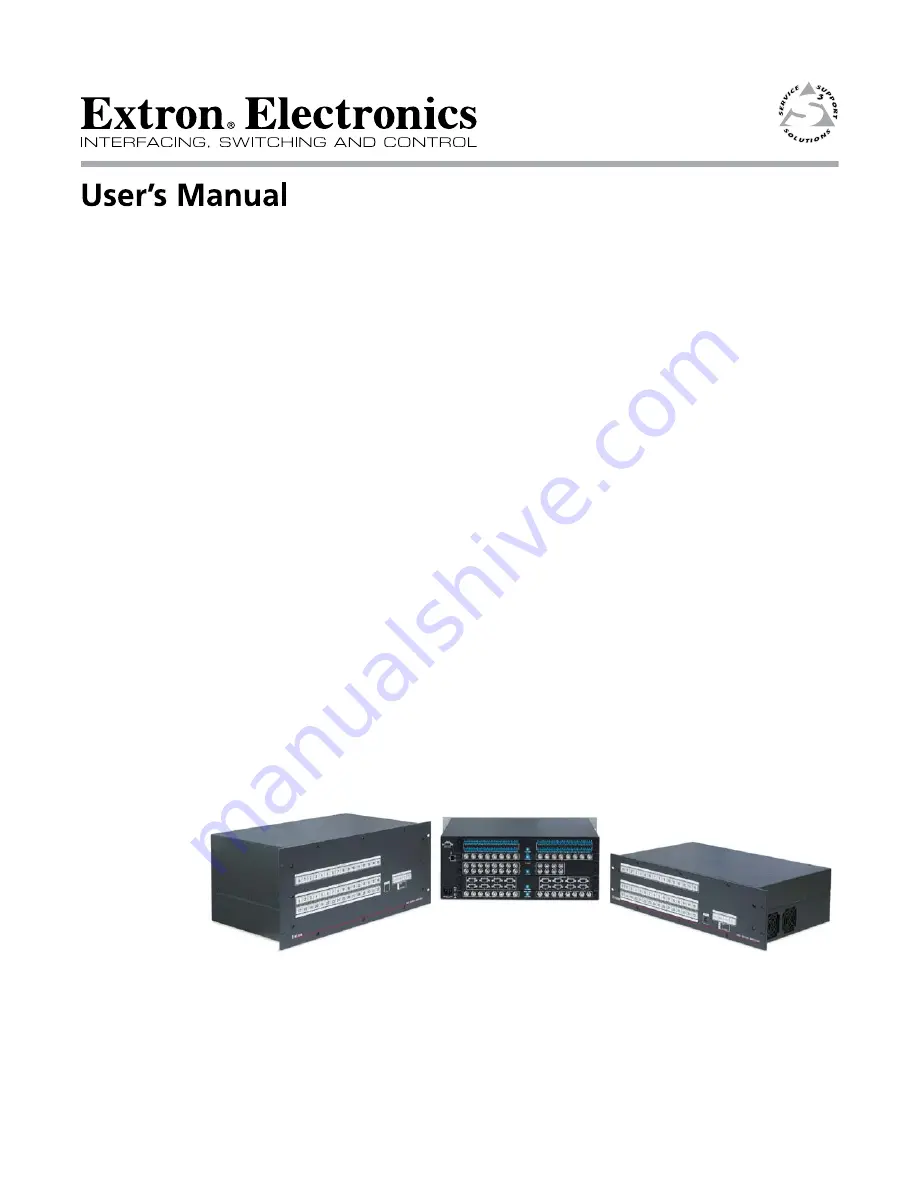
MultiMatrix Switcher 

68-1452-01 

Rev. A

10 09

Summary of Contents for 60-1021-01

Page 1: ...SMX System MultiMatrix Switcher 68 1452 01 Rev A 10 09 ...

Page 2: ...enden sollten Sie alle Sicherheits und Bedienungsanleitungen genau durchlesen und verstehen Aufbewahren der Anleitungen Die Hinweise zur elektrischen Sicherheit des Produktes sollten Sie aufbewahren damit Sie im Bedarfsfall darauf zurückgreifen können Befolgen der Warnhinweise Befolgen Sie alle Warnhinweise und Anleitungen auf dem Gerät oder in der Benutzerdokumentation Keine Zusatzgeräte Verwende...

Page 3: ...nce when the equipment is operated in a commercial environment This equipment generates uses and can radiate radio frequency energy and if not installed and used in accordance with the instruction manual may cause harmful interference to radio communications Operation of this equipment in a residential area is likely to cause harmful interference in which case the user will be required to correct ...

Page 4: ...ork cable 2 5 Ethernet cable termination 2 6 Input output boards 2 6 Wiring the audio connectors 2 8 Chapter Three Operation and Setup 3 1 Front Panel Features 3 2 I O plane selection buttons 3 2 Input and output buttons 3 2 Control buttons 3 3 Power indicator LED s 3 4 Front panel configuration port 3 4 Powering up 3 4 Front Panel Operation 3 5 Ties General information 3 5 Creating ties 3 5 Viewi...

Page 5: ...2 Default IP addresses 4 2 Establishing a connection 4 2 Connection Timeouts 4 3 Number of connections 4 3 Using Verbose Mode 4 3 Host to Switcher Instructions 4 3 Switcher Initiated Messages 4 3 Switcher Error Responses 4 4 Using the Command Response Table for SIS Commands 4 5 Symbol definitions 4 5 Command response table for SIS commands continued 4 9 Command response table for SIS commands cont...

Page 6: ...put 5 18 IP settings options 5 18 Setting the IP address 5 19 Setting the Extron name or descriptor 5 19 Setting the gateway IP address 5 20 Setting the subnet mask 5 20 Hardware address field 5 20 Enabling disabling DHCP 5 20 Setting the date 5 21 Setting the local time 5 21 Sync Time to PC button 5 21 Setting the offset from GMT 5 21 Enabling daylight savings time 5 21 Setting the administrator ...

Page 7: ... 6 7 Passwords page 6 8 Email Settings page 6 9 Mail IP Address field 6 9 Domain Name field 6 9 SMTP Authorization Required field 6 9 Email Address fields 6 10 Firmware Upgrade page 6 11 File Management Page 6 12 Uploading files 6 13 Adding a directory 6 13 Other file management activities 6 13 Control Pages 6 14 User Control page 6 14 To set or replace ties 6 14 To remove ties 6 15 To set input a...

Page 8: ...net tips A 6 Connecting to the SMX Open command A 6 Escape character and Esc key A 7 Local echo A 7 Setting carriage return line feed A 7 Closing the link to the switcher A 7 Help A 7 Exiting Telnet Quit command A 7 Subnetting A Primer A 8 Gateways A 8 Local and remote devices A 8 IP addresses and octets A 8 Subnet masks and octets A 8 Determining whether devices are on the same subnet A 9 Appendi...

Page 9: ...SMX System MultiMatrix Switchers 1 Chapter One Introduction About this Manual About the SMX MultiMatrix Switcher Definitions Features ...

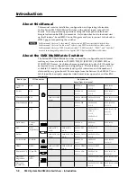
Page 10: ...ist of available I O boards the number and type of connectors and the number of slots used by any given board For example from the first row the SMX 84 V is an 8x4 8 input by 4 output composite video board takes up one slot and has BNC connectors Board type I O Connector Board names Board Sizes slots used Composite Video BNC SMX 84 V 8x4 1 SMX 88 V 8x8 1 SMX 1616 V 16x16 2 S video BNC SMX 84 YC 8x...

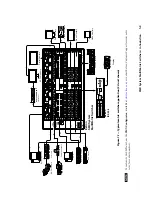
Page 11: ...CONFIG PROGRAM PREVIEW EFFECTS MENU NEXT DETAIL ZOOM BRIGHT CONT COLOR TINT SIZE CENTER TAKE CUT PIP TITLE WIPE DISSOLVE LOGO 2 BLACK LOGO 1 BLACK 1 2 3 4 5 6 1 2 3 4 5 6 LOGO 2 BLACK LOGO 1 BLACK FREEZE FREEZE Video Recorders Main Projection Display Extron SMX System MultiMatrix Switcher Extron ISS 506 Sound Systems DVI Equipped PCs HDTV Monitors Compact HDTV Camera Systems Video Monitors PCs DVD...

Page 12: ...d Display Identification Data A communications protocol or instruction set developed by VESA Video Electronics Standards Association for the identification of display devices to computers using the DDC Display Data Channel transmission standard HDCP High bandwidth Digital Content Protection An encryption method developed by Intel that protects copyrighted digital entertainment material that uses t...

Page 13: ...rix switcher the I O configuration may then be saved for future downloading to the matrix switcher IP Control Ethernet via the LAN port This port allows the switcher to be controlled through an Ethernet local area network LAN and or wide area network WAN using standard IP internet protocols This ability provides flexible connectivity for off site control and password protection of the switcher Web...

Page 14: ...l system The Ethernet link allows multiple remote links with two levels of password protection Front Panel Controller The front panel controller supports input and output selection I O grouping preset creation and selection RGB delay and audio gain and attenuation and volume control audio models The front panel features illuminated push buttons that can be labeled with text or graphics Windows bas...

Page 15: ...SMX System MultiMatrix Switchers 2 Chapter Two Installation U L Safety Requirements Mounting the Switcher Rear Panel Features and Connections ...

Page 16: ... a third grounding prong The wide blade or the third prong are provided for your safety If the provided plug does not fit into your outlet consult an electrician for replacement of the obsolete outlet 10 Protect the power cord from being walked on or pinched particularly at plugs convenience receptacles and the point where they exit from the apparatus 11 Only use attachments accessories specified ...

Page 17: ...greater than room ambient temperature Therefore install the SMX in an environment compatible with the maximum ambient temperature Tma 122 F 50 C specified by Extron 2 Reduced air flow Install the equipment in a rack so that the amount of air flow required for safe operation of the equipment is not compromised 3 Mechanical loading Mount the equipment in the rack so that a hazardous condition is not...

Page 18: ... PLAN E ADR ESS INP UT S 1 2 3 4 OU TPU TS 1 2 3 4 PLAN E ADR ESS CO MP UT ER IN 5 6 7 8 1 2 3 4 CO MP UT ER OU T 5 6 7 8 1 2 3 4 PLAN E ADR ESS VID EO OU TPU TS 16 15 9 12 13 14 11 10 VID EO INP UT S 16 15 9 12 13 14 11 10 16 15 9 12 13 14 11 10 16 15 9 12 13 14 11 10 S VID EO Y C Y C Y C IN PLAN E ADR ESS 9 10 11 12 13 14 15 16 L R L R L R L R L R L R L R L R L 1 R L 2 R L 3 R L 4 R L 5 R L 6 R ...

Page 19: ...ource into this receptacle b LAN Ethernet port Connect the switcher to an Ethernet LAN or WAN via this RJ 45 connector Ethernet control allows the operator to control the switcher from a remote location When connected to an Ethernet LAN or WAN the switcher can be accessed and operated from a computer running a standard Internet browser Ethernet connection indicators The LEDs marked Link and Act in...

Page 20: ... communication protocol and can operate at 9600 19200 38400 or 115200 baud rates See chapter 3 Operation and Setup to configure the RS 232 RS 422 port Input output boards N All boards are hot swappable and can be installed without shutting down the switcher and removing the power see page 2 4 The I O boards on any unit may vary with each installation depending on desired configuration and use All ...

Page 21: ...Connect composite video input signals to the BNC input connectors Connect display devices to the BNC output connectors 8 7 1 4 5 6 3 2 1 4 3 2 VIDEO OUTPUTS VIDEO INPUTS ADDRESS VIDEO l SMX 88 A Connect stereo or mono audio input signals to any of the eight sets of 3 5 mm 5 pole captive screw connectors marked Inputs Wire the connector for the appropriate signal type as shown on page 2 8 ADDRESS I...

Page 22: ...no audio connector consists of the tip and sleeve whereas a stereo audio connector consists of the tip ring and sleeve The tip ring and sleeve wires are also shown above on the captive screw audio connector diagram balanced inputs figure 2 6 Tip Sleeve Sleeve Ring Tip RCA Connector 3 5 mm Stereo Plug Connector balanced Figure 2 7 RCA audio connectors Wire the output connectors as shown below Unbal...

Page 23: ... 3 Chapter Three Operation and Setup Front Panel Features Powering Up Front Panel Operation Rear Panel RS 232 RS 422 Communications Viewing and Adjusting the Audio Input Level Viewing and Adjusting the Audio Output Volume Reset Levels ...

Page 24: ...r status LEDs c Output selection buttons 1 16 f Front panel configuration port I O plane selection buttons a Plane selection buttons The buttons labeled 0 through 15 allow plane selection and identify any tied inputs and outputs on the selected plane These correspond to the board rotary switch settings Input and output buttons b Input selection buttons The Input 1 through Input 16 buttons select i...

Page 25: ...n combination the following functions are available Control button combination Function ENTER PRESET VIEW ESC Selects serial port configuration PRESET VIEW ESC Toggles between Executive modes 2x and 0x VIEW ESC Toggles between Executive modes 2x and 1x N See Rear Panel RS 232 RS 42 Communications section for serial port configuration details See Setting the front panel locks Executive modes sectio...

Page 26: ...led Main and I O cards light green when power is applied to the unit Front panel configuration port f Configuration port This 2 5 mm port jack can be used to configure the SMX during setup via RS 232 and has an independent protocol from the primary RS 232 port on the rear panel Use the 2 5 mm configuration cable part 70 335 01 see figure 3 2 for connection to your PC s serial port RS 232 protocol ...

Page 27: ...utton an existing tie is toggled off by pressing the button and the Enter is pressed the existing tie to that output is lost Ties can also be made using SIS commands via RS 232 or Telnet HTTP or by using the SMX s Control Software program or it s internal Web pages See chapter 4 Programmer s Guide for RS 232 methods chapter 5 SMX Control Software for Software methods and chapter 6 HTML Operation f...

Page 28: ... input output and Enter buttons all extinguish N If the Enter button extinguishes before being pressed repeat steps 2 to 5 Viewing ties Any existing input to output tie can be viewed An example of viewing a set of video or audio ties The following steps show how to view existing ties on any allocated plane here planes 0 and 2 1 Press the View button lights red The last plane button used here 0 lig...

Page 29: ...ties Any video or audio tie can be removed from an existing set of ties An example of removing ties from an existing set of video or audio ties In this example Input 3 on video plane 0 is already tied to output s 2 4 6 and 7 The ties to outputs 4 and 7 are to be removed 1 Press and release plane button 0 lights green Input button 1 lights the plane signal type green for video red for audio amber f...

Page 30: ... type green for video red for audio amber for both 2 Press and release Input button 7 lights Tied outputs s 3 and 6 light the same color as the input button Input 1 extinguishes 3 Press and release output 1 button This button blinks the same color as the input button and the Enter button blinks green The other tied buttons s 3 and 6 remain lit see figure 3 13 Step 1 Press and release the I O Plane...

Page 31: ... Step 3 Press and release the desired I O Plane here plane 2 The plane button and any untied outputs light Muted outputs flash Tied outputs remain unlit I O PLANE SELECT 1 2 3 4 5 6 7 8 9 10 11 12 13 14 15 0 The last plane button used lights Figure 3 10 Steps 2 and 3 for muting output signals 3 Select the applicable plane lights The output buttons light if untied or flash if tied and muted the sig...

Page 32: ...d to any one of the preset locations in any order Saving the current configuration to an existing preset overwrites the existing preset in favor of the new configuration 1 2 3 4 5 6 7 8 9 10 11 12 13 14 15 16 INPUTS 1 2 3 4 5 6 7 8 9 10 11 12 13 14 15 16 OUTPUTS 1 5 6 10 7 13 14 15 2 8 9 3 4 11 12 16 GLOBAL 1 5 6 10 7 2 8 9 3 4 PLANE 17 21 22 26 23 29 30 31 18 24 25 19 20 27 28 32 GLOBAL Figure 3 ...

Page 33: ...r output button to select the address to save the current configuration to Address Preset and Enter buttons flash red N Any lit or unlit button can be selected to save a preset to Only lit presets can be recalled When saving to a lit previously saved preset the stored data is overwritten with the new data Only one preset address can be selected and saved to at a time 4 Press and release the Enter ...

Page 34: ...e front panel when in Lock modes 1 and 2 1 Press the Esc button to clear all pending changes flashes green once 2 Select a VGA or RGBHV plane 3 Press and hold View for 3 seconds The selected plane button flashes green 4 Select the output to delay button lights 5 Using View and Esc adjust the time duration for the delay up to 5 seconds maximum Each lit input button corresponds to half a second dela...

Page 35: ...n Lock mode 0 this procedure selects mode 2 Preset View and Esc buttons flash green twice If it is in Lock mode 2 this procedure selects mode 0 unlocks the switcher View and Esc flash green twice Toggle the lock on or off by pressing and holding the Preset View and Esc buttons simultaneously for approximately 2 seconds Press and hold for about 2 seconds C O N T R O L ESC VIEW PRESET ENTER Exec mod...

Page 36: ...ne buttons 0 and 1 light 2 Use the control buttons to select the baud rate Enter 9600 Preset 19200 View 38400 Esc 115200 The selected baud rate button flashes 3 Use the I O plane buttons 0 and 1 to select the connection type I O plane button 0 RS 232 I O plane button 1 RS 422 The selected connection type button flashes 4 Press any input or output button to exit configuration mode Viewing and Adjus...

Page 37: ... be set by selecting each input button 7 Press and release the Enter button or wait for 30 seconds to exit the audio display and adjustment mode The audio plane button extinguishes N There is only one audio level setting per input on a specific plane The audio level is shared by the left and right audio inputs The audio levels are stored in non volatile memory When power is removed and restored th...

Page 38: ...or decrease the output audio volume see figure 3 21 for settings 6 Additional outputs can be set by selecting each output button 7 Press and release the Enter button or wait for 30 seconds to exit the audio display and adjustment mode The audio plane button extinguishes INPUTS 1 2 3 4 5 6 7 8 9 10 11 12 13 14 15 16 OUTPUTS 1 2 3 4 5 6 7 8 9 10 11 12 13 14 15 16 INPUTS 1 2 3 4 5 6 7 8 9 10 11 12 13...

Page 39: ...ly 58 43 0 38 flash slowly 26 89 5 7 flash slowly 57 41 5 39 flash slowly 25 88 0 8 14 56 40 0 40 6 24 86 5 9 14 55 38 5 41 6 23 85 0 10 flash slowly 54 37 0 42 flash slowly 22 83 5 11 flash slowly 53 35 5 43 flash slowly 21 82 0 12 13 52 34 0 44 5 20 80 5 13 13 51 32 5 45 5 19 79 0 14 flash slowly 50 31 0 46 flash slowly 18 77 5 15 flash slowly 49 29 5 47 flash slowly 17 76 0 16 12 48 28 0 48 4 1...

Page 40: ...on that results from the mode 1 reset If you want to use the factory default firmware you must upload that version again If you do not want to update firmware or you performed a mode 1 reset by mistake cycle power to the switcher to return to the firmware version that was running before the mode 1 reset Use the 0Q SIS command to confirm that the factory default firmware is no longer running look f...

Page 41: ...n earlier firmware version 3 Hold down the Reset button for about 3 sec until the Power LED blinks once then release and press Reset momentarily 1 sec within 1 second 4 Hold down the Reset button for about 6 sec until the Power LED blinks twice once at 3 sec again at 6 sec Then release and press Reset momentarily for 1 sec within 1 second 0 Nothing happens if the momentary press does not occur wit...

Page 42: ...ammer s Guide RS 232 RS 422 Link Ethernet LAN Port Host to Switcher Instructions Switcher Initiated Messages Switcher Error Responses Using the Command Response Table for SIS Commands Command Response Table for SIS Commands Command Response Table for IP SIS Commands ...

Page 43: ...ted for your application See page A 2 for cable termination details Default IP addresses To access the SMX switcher via the Ethernet port you need the Extron IP address and may need the subnet mask and the gateway address If the IP address has been changed to an address comprised of words and characters the actual numeric IP address can be determined using the ping ICMP utility see appendix A Ethe...

Page 44: ... SIS command responses Host to Switcher Instructions The SMX accepts SIS commands through the RS 232 RS 422 and Ethernet ports SIS commands consist of one or more characters per command field They do not require any special characters to begin or end the command character sequence Each switcher response to an SIS command ends with a carriage return and a line feed CR LF which signals the end of th...

Page 45: ...f from the front panel pp is the plane address nn is the output number and x is the mute status 1 on 0 off ppAmtnn x The switcher initiates the Amt message when an audio output mute is toggled on or off from the front panel pp is the plane address nn is the output number and x is the mute status 1 on 0 off Exen The switcher initiates the Exe message when executive mode is toggled on or off from th...

Page 46: ...put numbers are reported as 2 digit numbers in the response e g 03 for input 3 X Input number 1 through maximum number of inputs X Input number for ties 0 through maximum number of inputs N Input 0 untied X Output number 1 through maximum number of outputs X Numeric dB value 18 through 24 43 steps of gain or attenuation X Audio gain 0 dB through 24 dB X Audio attenuation 1 dB through 18 dB X Volum...

Page 47: ...5 for 16 planes 90 to 99 for virtual planes 10 planes X2 Voltage positive or negative voltage magnitude X2 Temperature Degrees Fahrenheit X2 Fan speed RPM X2 Create virtual plane address 90 99 10 planes X3 Slot number 1 6 3U 1 8 4U 1 10 5U 00 e mail F P 1 10 e mail I X3 Slot information XYZ X board type B T plus X YZ board size 00 15 X Board Type X Board Type B Video L DVI C S video M DVI D S vide...

Page 48: ...0p default 2 channel audio 60 12 800x600 75 33 1080i 50 1080p multi channel audio 60 13 852x480 60 34 1080i 60 1080i 2 channel audio 60 14 852x480 75 35 1080p 50 1080p 50 15 1024x768 default DVI 60 36 1080p 60 1080p 2 channel audio 60 16 1024x768 75 37 User assigned 17 1024x852 60 38 User assigned 18 1024x852 75 39 User assigned 19 1280x768 60 40 User assigned 20 1280x768 75 N In the table above t...

Page 49: ...r video can be used interchangeably Tie input to all RGBHV X2 X X2 InX RGB Tie input X to all outputs on planeX2 for RGB signals Tie input to all video X2 X X2 InX Vid Tie input X to all outputs on plane X2 for video signals Tie input to all audio X2 X X2 InX Aud Tie input X to all outputs on plane X2 for audio signals Tie input to all audio and video X2 X X2 InX All Tie input X to all outputs on ...

Page 50: ... plane X2 View mute View output mutes entire plane E X2 VM X1 1X1 2 X1 n View output mute for plane X2 Mut X2 X1 1X1 2 X1 n in verbose mode 2 or 3 RGB Delay Triple Action Switching for VGA RGBHV only Set RGB Delay by plane EX2 X X1 D X2 OutX DlyX1 Read RGB Delay E X2 X D X1 Global presets all planes Save current ties as a global preset X1 SprX1 Save the current set of ties as global preset X1 The ...

Page 51: ...ode 2 or 3 VppX2 X1 OutX X 1 X 2 X 3 X 4 X 16 Vid View plane presets audio EPX2 X1 X 2 VC X 1 X 2 X 3 X 4 X 16 Aud View audio configuration Verbose mode 2 or 3 VppX2 X1 OutX X 1 X 2 X 3 X 4 X 16 Aud N 1 If preset is unassigned then name displays unassigned 2 If a global preset is saved but not yet named then default name is Preset X1 X1 preset number 3 If user tries to name when preset is not save...

Page 52: ... 3Q 4Q verbose response N The firmware that is currently running is marked by an asterisk A question mark indicates that only factory firmware is loaded A caret indicates the firmware that should be running but a Mode 1 reset was executed and the default factory version is loaded An exclamation point indicates corrupted firmware Example 0Q Ethernet protocol firmware Response Description SMX firmwa...

Page 53: ...ription short verbose mode 2 or 3 e g Inf 01 SMX Matrix Switcher Query model description 2I Switcher description long Inf 02 Switcher description long verbose mode 2 or 3 e g Inf 02 SMX Matrix Switcher Configurable Multi Switcher Query system memory usage 3I of Bytes used out of KBytes Inf 03 of Bytes used put pf KBytes Query user memory usage 4I of Bytes used out of KBytes Inf 04 of Bytes used pu...

Page 54: ... VGA board G no board 0 n5 Slot 5 G00 Slot 5 is covered by VGA board G no board 0 n6 Slot 6 G15 VGA board G 1616 configuration 15 4 slots board n7 Slot 7 D00 Slot 7 is covered by S video BNC board top D no board 0 n8 Slot 8 D15 S video BNC top board D 1616 configuration 15 2 slots top of 4 n9 Slot 9 C00 Slot 9 is covered by S video BNC board bottom C no board 0 n10 Slot 10 C15 S video BNC top boar...

Page 55: ... 26 1366x768 75 6 Output 6 27 1400x1050 60 7 Output 7 28 1600x1200 60 8 Output 8 29 480p 60 480p 2 channel audio 60 9 640x480 60 30 576p 50 576p 50 10 640x480 75 31 720p 50 720p 50 11 800x600 60 32 720p default DVI Pro HDMI 60 720p default 2 channel audio 60 12 800x600 75 33 1080i 50 1080p multi channel audio 60 13 852x480 60 34 1080i 60 1080i 2 channel audio 60 14 852x480 75 35 1080p 50 1080p 50 ...

Page 56: ...lot X3 X LS X1 X3 FRQX X1 Verbose mode 2 or 3 N Unit responds 0000 if no connection or error is found List all sync DVSP slot X3 0LS X1 1X1 2 X1 n X3 FRQ0 X1 1X1 2 X1 n Verbose mode 2 or 3 DSVP link present for Fiber optic boards List all input DVSP X3 0LS X1 1X1 2 X1 n X3 FRQ0 X1 1X1 2 X1 n Verbose mode 2 or 3 N List individual signal present per slot is not available on this board Unit responds ...

Page 57: ...rement X2 X V X2 OutX VolX Decrement X2 X V X2 OutX VolX Output level X2 X X V X2 OutX VolX View Audio levels Audio gain for input X2 X G X Audio volume for output X2 X V X Names N Invalid characters for names are and The name may have up to 12 characters including A Z a z 0 9 and space Write global preset name EX1 nameNG NmgX1 name Assign name to preset X1 Example E1 Security1NG Nmg01 Security1 N...

Page 58: ...1 Clear plane preset X1 Reset All RGB Delay to 0 seconds E ZD Zpd Reset RGB Delay to zero Reset RGB Delay entire plane E X2 ZD X2 Zpd Reset RGB Delay to zero Reset all audio gains to 0 dB E ZA Zpa Reset all audio gains to zero Reset audio gains to 0 dB for entire plane E X2 ZA X2 Zpa Reset all audio gains to zero Reset all audio volume to 100 E ZV Zpv Reset all volume to 100 Reset all audio volume...

Page 59: ... day 01 through 31 YY year 00 through 99 HH hour 00 through 23 MM minutes 00 through 59 SS seconds 00 through 59 X5 IP Gateway address N Factory default IP Gateway address 192 168 254 254 X5 Email domain name Standard name conventions apply e g xxx com N The following characters are invalid in a domain name space and The character is only acceptable as lead in to the domain name such as extron com...

Page 60: ...ge 1 to 127 max X8 E mail event number mailbox range 1 to 64 max Response is 3 digits with leading zeros X8 E mail recipient address X8 E mail account 65 72 X8 Notification Selection 1 I inputs F fans P power supply X8 Notification Selection 2 If X8 I then X8 00 all inputs or 1 to 16 If X8 F then X8 00 both fans or 01 fan 1 or 02 fan 2 If X8 P then X8 00 both power supplies or 01 PS 1 or 02 PS 2 X...

Page 61: ...T IptX5 Read time and date ECT X5 Set GMT offset EX5 CZ IpzX5 N In the command the divider between hours and minutes can be either a colon or a period In the response the divider is a colon Example E8 0CZ Ipz 08 00 Read GMT offset ECZ X5 Set Daylight Saving Time EX7 CX IpxX7 Read Daylight Saving Time ECX X7 Set DHCP on E 1DH Idh1 Set DHCP on Set DHCP off E 0DH Idh0 Set DHCP off N Setting DHCP from...

Page 62: ...onses enabled Set mail server IP unit domain name EX5 X5 X7 X7 CM Ipm X5 X5 X7 X7 X7 Password 12 digits user admin N Password is optional If no password is being used type EX5 X5 CM Read mail server IP domain name ECM X5 X5 X7 X7 Set e mail recipient EX8 X8 CR IprX8 X8 Read e mail recipient EX8 CR X8 Show e mail recipient address X8 Set E mail events for recipient EX8 X8 X9 X8 X8 EM X8 IpeX8 X8 X8...

Page 63: ...e ECY X7 Set current conn port timeout E0 X8 TC Pti0 X8 Read current conn port timeout E0TC X8 Configure global IP port timeout E1 X8 TC Pti1 X8 Read global IP port timeout E1TC X8 N X5 Specific port number 01 02 X6 Baud rate 9600 default 19200 38400 115200 X6 Parity Odd even none mark space only first letter required X6 Data bits 7 8 X6 Stop bits 1 2 X7 Port type 0 RS 232 default 1 RS 422 X8 The ...

Page 64: ...PRELIMINARY SMX System MultiMatrix Switchers 5 Chapter Five SMX Control Software Installing and Starting the SMX Control Program Using the Program Special Characters Using the Button Label Generator ...

Page 65: ...trol Program The switcher can be operated via the Windows based SMX Control Program This program is contained on the Extron Software Products DVD included with the switcher Install and run this program on a Windows based PC connected to either of the switcher s serial ports or the Ethernet port See b and d on pages 2 5 and 2 7 for connection information It cannot be run from the DVD Installing the...

Page 66: ...ange the baud rate click the Baud button double click the desired baud rate Click OK Proceed to Using the program section If you selected IP LAN click OK and proceed to step 3 If you selected Emulate click OK and see Using emulation mode later in this chapter 3 If you selected IP LAN in step 2 the IP Connection window opens a Examine the IP Address field which displays the last IP address entered ...

Page 67: ...ies If an incorrect password is entered the program beeps and returns to the password entry display Using the program At startup the SMX Control Program window figures 5 1 appears The window displays the current configuration of the SMX with numbered boxes representing the video and or audio inputs and outputs and opens at plane 0 Each plane has a separate numbered tab from 0 15 here only planes 0...

Page 68: ...ed some menus submenus and buttons may appear grayed out and are not selectable Control program menus and pages There are six top level menu items on the menu bar File Tools Audio input Config Preferences Master Reset and Help File This drop down menu see figure 5 3 has the following items Save Matrix settings as Restore Matrix settings from Save This Session s settings Restore Last Session s sett...

Page 69: ...he available printers connected to the PC Print Tie Maps Select this to print the tie map in the active window to the default or currently selected printer Exit Select this to close the SMX control program Current settings are maintained and loaded upon restart N Alternatively click on the red X in the top right corner to close the SMX Control Program Tools This drop down menu see figure 5 4 has t...

Page 70: ...RGB Delay slider to set the desired delay in 0 5 second steps Click Take to accept the change or click Cancel to return the delay to its original setting Click Close to exit the window N This menu also contains Mute Output settings See Mute Output settings below for method Audio Input Gain settings Select this to change the audio gain 0 5 dB steps for all or single inputs To change the gain select...

Page 71: ...audio outputs To mute a video or audio signal select an output or all and check the video and or audio mute box The output is now muted and the output box in the main window indicates the mute status Click Close to exit the window N When connected to an RGB input this menu also shows RGB Delay settings See RGB Delay settings above for method HD SDI Re clocker Rate settings Select this to reset the...

Page 72: ...aded from the Extron website www extron com To download the latest firmware file to your computer 1 On the Extron Web page select the Download tab 2 Click the Firmware link on the left sidebar menu 3 Click on S scroll to SMX switcher and click Download 4 Fill in the required information then click Download product name_ firmware version exe 5 In the File Download Security Warning window click Save...

Page 73: ...ttings Click Close to close the window N Fields that appear grayed out have been set at the factory are not changeable To change the Date Time settings complete the applicable fields or click the Sync time to PC button To create change the Administrator User passwords edit the applicable fields N An administrator password must be created before a user password can be The characters and space are i...

Page 74: ...tion and firmware details Click Update to refresh the window with real time information Click Close to exit the window Physical switchers config Select this to view the I O board types sizes per slot Virtualize Select this to view and set up to 10 virtual planes After selecting Take new tabs for the virtual planes here planes 1 and 5 appear on the inputs page ...

Page 75: ...til an audio plane is selected Upon selection of this menu one window Configure Audio Options opens Configure Audio Options Opening this window allows the user to set the dB gain per audio input Click on the applicable Changes radio buttons to have the changes either Immediate or verifiable Verify default setting allows accepting the changes via a Take button Immediate removes the Take button from...

Page 76: ... down menu has the following selectable items Immediate Changes Hold Verify Changes Ties as Lines Ties as Crosspoints Frequency read options Icons in I O boxes Numbers in I O Boxes and Catch FPC other s Changes Select or deselect an item as required When selected a check mark is visible Immediate Changes Selecting this allows input to output tie changes to happen immediately without the need to us...

Page 77: ...ead options setting is None then Tools View Input Frequencies is grayed out and not available Icons in I O Boxes Select this to reserve the choice of showing user assigned icons or in sequential See the Customizing the SMX window section earlier in this chapter Numbers in I O boxes Select this to have the input output number displayed in the boxes Catch FPC other s changes Select this to have the ...

Page 78: ...del type and slot count here a 3U SMX with 6 slots and front panel control Board signal configuration here 8x8 video inputs and outputs Firmware version here 1 10 Login mode here logged in as administrator and Unit connection here COM 1 at 9600 baud rate Select Firmware to open two windows The first shows the SMX s main firmware version and build number here version 1 10 build 0002 The second wind...

Page 79: ...on from the devices screen to an input or output box on the program window Repeat for additional devices as desired 3 In the Caption box enter a caption e g Laptop for the device if desired This caption appears in the descriptive window that pops up when you pass the cursor over an input or output box containing an icon Figure 5 7 Pop up window for input 1 containing a caption 4 When finished assi...

Page 80: ...e tie The broken line becomes solid Figure 5 8 Completed ties solid and pending ties broken lines If Immediate Changes has been selected in the Preferences menu the tie is made immediately a solid line appears and Cancel or Take buttons are not displayed To remove a tie Drag the output box outline to its tied input box or to the trash can If Hold Verify Changes has been selected from the Preferenc...

Page 81: ...nal being sent to or from it see figure 5 9 Figure 5 9 Matrix window section with output 2 pop up information IP settings options The IP Settings Options window figure 5 10 lets you view and if connected via the RS 232 RS 422 link or if you are logged on via the Ethernet port as an administrator editing settings unique to the Ethernet interface None of the fields on this screen can be edited while...

Page 82: ...s is 192 168 254 254 but if this conflicts with other equipment at your installation you can change the IP address to any valid value Edit the address field as follows 1 Click in the Matrix IP address field The graphic cursor becomes a text cursor 2 Make any desired changes to the address 3 Press the Tab key on the keyboard or click in another field to exit the Matrix IP Address field 4 Click the ...

Page 83: ... server when you are subnetting The subnet mask has the same format as the Matrix IP and Gateway addresses For more information see Subnetting A Primer in appendix A Ethernet Connection Edit this field as follows 1 Click in the Subnet Mask field The graphic cursor becomes a text cursor 2 Make any desired changes to the mask 3 Press the Tab key on the keyboard or click in another field to exit the ...

Page 84: ...Take button to make the time change take effect Sync Time to PC button Clicking the Sync Time to PC button causes the computer you are operating to send its internal time to the switcher in a set time command Setting the offset from GMT The GMT field displays the amount of time in hours and minutes that the local time varies from the GMT international time reference If necessary adjust the offset ...

Page 85: ...Passwords are case sensitive and are limited to 12 uppercase and or lowercase alphanumeric characters While you are logged on as a user this field is masked with asterisks as a security measure N An administrator password must be created before a user password can be created N The following characters are invalid in passwords and space Edit this field as follows 1 Click in the User Password field ...

Page 86: ...ain Name field 4 Click the Take button to make the name change take effect Entering e mail addressee information The eight E mail Addressee fields permit the administrator to identify the e mail addresses of the personnel to whom the SMX switcher e mails notification of its failure and repair status Figure 5 15 shows a typical e mail from the switcher Figure 5 15 Typical SMX e mail The radio butto...

Page 87: ...ct Updating the firmware The firmware upgrade utility provides a way to replace the firmware that is coded on the SMX s control board without needing to take the switcher out of service open its enclosure and replace the firmware chip Update the SMX firmware as follows N The update firmware utility is for replacing the firmware that controls all switcher operation This is not the page to insert yo...

Page 88: ...ion is not a firmware upgrade N The original factory installed firmware is permanently available on the SMX switcher If the attempted firmware upload fails for any reason the switcher reverts to the factory installed firmware 5 Click Open A confirmation prompt window opens reminding you that loading the selected s19 file will reprogram the device s firmware 6 Click OK to continue with the upload A...

Page 89: ... and space 1 Connect the PC to the SMX via the switcher s RS 232 RS 422 port or Ethernet port 2 Start the Matrix Switcher Control Program and connect to the SMX switcher See Using the program in this chapter for the procedure 3 From the Tools menu select HTML File Manager The HTML Files List window opens 4 Click the Pick File s to Load to Server button The Select files window opens 5 Navigate to t...

Page 90: ... by clicking Delete Go Activates the selected preset as the current configuration Save as Allows the current set of ties to be saved as a global or plane preset Enter the preset number when prompted to do so Delete Allows the selected global or plane preset to be deleted Take Allows you to save to file any changes made to the displayed configuration Cancel Returns to the previous screen undoing an...

Page 91: ...PRELIMINARY SMX System MultiMatrix Switchers 6 Chapter Six HTML Operation Accessing the Web Pages System Status Pages Configuration Pages File Management Page Control Pages Special Characters ...

Page 92: ...actory specified default 192 168 254 254 is the correct value for this field 4 If you want the browser to display a page other than the default page such as a custom page that you have uploaded enter a slash and the name of the file to open N The browser s Address field should display the address in the following format xxx xxx xxx xxx optional_file_name html N The following characters are invalid...

Page 93: ...y of the four main pages System Status Configuration File Management and Control can be accessed at any time by clicking on the relevant tab Each main page has a series of sub pages accessible through the named links in the sidebar menu System Status Pages The System Status pages give access to sub pages System Status the default page Physical Configuration and DVSP To view each individual page cl...

Page 94: ...s the installed board function or type VGA DVI etc board size 8x8 multi slot etc and the plane address allocated to that board see figure 6 3 Figure 6 3 Physical configuration page DSVP The Digital Sync Validation Processing DSVP page displays the current signal status and source of connected video inputs per board For VGA RGBHV boards the horizontal and vertical frequencies per slot is also shown...

Page 95: ...trators have full access to all switching capabilities and editing functions Users can create ties create and recall presets and view all settings with the exception of passwords Ethernet connection to the switcher either entering SIS commands see chapter 4 Programmer s Guide or using the Matrix Switcher Control Program see chapter 5 SMX Control Software is password protected Connection via the RS...

Page 96: ...r equipment at your installation you can change the IP address to any valid value N IP address changes can cause conflicts with other equipment Only local system administrators should change IP addresses Gateway IP Address field The Gateway IP Address field identifies the address of the gateway to the mail server to be used if the switcher and the mail server are not on the same subnet The gateway...

Page 97: ...to then enter the offset from Greenwich Mean Time GMT N The Zone field identifies the standard time zone that has been selected and displays the amount of time in hours and minutes that the local time varies from the GMT international time reference 4 Repeat steps 1 through 3 for other variables that need to be changed 5 Select the appropriate Daylight Saving radio button To turn off daylight savi...

Page 98: ...ain in the Re enter Password field to the right Characters in these fields are masked by four bullets If you do not want to password protect an access level leave the Password and the Re Enter password fields blank After entering the desired password in both fields click the Submit button at the bottom of the page N An administrator password must be created before a user password can be created So...

Page 99: ...d can be numbered from 000 through 255 Leading zeroes up to 3 digits total per field are optional Values of 256 and above are invalid Domain Name field The Domain Name field displays the domain name that the SMX switcher uses to log on to the e mail server Standard domain name conventions for example nnnnn xxx com apply N The following characters are invalid in a domain name and space The characte...

Page 100: ...ddresses of the personnel to whom the SMX switcher e mails notification of its failure and repair status Standard e mail address conventions nnnnn xxx com apply The check boxes and drop boxes associated with each address field let you specify specific criteria under which the SMX will e mail the recipients Click Edit to make changes Click Save to save the changes see figure 6 9 In the Missing Inpu...

Page 101: ...mputer a On the Extron Web page select the Downloads tab b On the Download Center page click the Firmware link on the left sidebar menu c Click on the name of your SMX switcher d On the next screen fill in the required information then click the Download product name_firmware version exe button e On the File Download Security Warning window click Save f On the Save As window browse to the folder w...

Page 102: ...ts to the factory installed firmware 7 Click Open 8 On the Firmware Upgrade page click the Upload button While the firmware is uploading the Upload button changes to Uploading When the uploading process is complete the button changes back to Upload The uploading may take a few minutes File Management Page This page allows the user to upload or delete user files such as HTML pages and bitmaps from ...

Page 103: ...le system follow these steps 1 Enter the directory name in the Dir field following the slash 2 Click the Add Dir button 3 With the directory name displayed perform the Uploading files procedure described in the previous section to add a file to the directory The directory name appears at the top of the Files column preceded by a slash To add more files to the directory click the directory name to ...

Page 104: ...gs on this page To set or replace ties 1 Select the desired plane from the drop down box see figure 6 13 N When selecting a plane only the available adjustment fields will show on the screen according to the output board type installed and addressed 1 2 3 Figure 6 13 Control pages User Control page 2 In the signal type field click Video only Audio only or Video Audio depending on the signal type t...

Page 105: ...om amber If a single signal tie video or audio is removed or a combined signal when the video audio signal type button is highlighted the button turns gray see figure 6 13 input 6 output 7 for example video and audio tie provisionally removed 4 Click Take to make the tie The screen refreshes the letter P disappears from the button and the SMX is updated removing the selected tie To set input audio...

Page 106: ...o 64 appears see figure 6 15 output 6 Figure 6 15 Click in an output field to see the drop down list 2 Scroll down to the desired level and click The page refreshes and the device updates to the selected level N Alternatively use the and buttons to increment or decrement the level just 1 step at a time The page refreshes every time the or buttons are clicked on and the device updates with each ste...

Page 107: ...utput to be muted The gray button changes color according to the muted signal see Note and figure 6 16 and shows muted The page refreshes and the SMX updates with the selection N If the output is muted for audio the button shows red If the output is muted for video the button shows green If the output is muted for video and audio the button shows amber Figure 6 16 A V mute buttons status according...

Page 108: ...tored from connected EDID monitors as reference 9 36 are factory fixed rates and 37 40 are user assignable User 1 37 User 2 38 User 3 39 User 4 40 See the EDID table on page 4 14 for the full list Figure 6 17 Click in an input field to see the drop down list 3 If using 37 40 click one of the Save Output 1 User buttons 1 4 as desired The DDC data is saved under the User number for recall 4 To save ...

Page 109: ...he plane preset field grays out 2 Select the desired preset by clicking one of the preset buttons To create a new preset click one of the unassigned buttons To overwrite an existing preset click its button 3 Enter a name for the preset in the text field N Preset names are limited to 12 characters Valid characters are 0 9 a z A Z _ and space The following characters are invalid in preset names and ...

Page 110: ...ers Valid characters are 0 9 a z A Z and special characters _ and space The following characters are invalid in preset names and 4 Click Accept If you do not rename an unassigned button the SMX names the preset as Preset nn where nn corresponds to the next plane number If you do not rename an existing preset when it is overwritten the SMX retains the same name Recalling a plane preset To recall a ...

Page 111: ...PRELIMINARY SMX System MultiMatrix Switchers A Appendix A Ethernet Connection Ethernet Link Subnetting A Primer ...

Page 112: ... white blue 6 green 6 green 7 white brown 7 white brown 8 brown 8 brown Crossover Cable for direct connection to a PC End 1 End 2 Pin Wire Color Pin Wire Color 1 white orange 1 white green 2 orange 2 green 3 white green 3 white orange 4 blue 4 blue 5 white blue 5 white blue 6 green 6 orange 7 white brown 7 white brown 8 brown 8 brown Figure A 1 RJ 45 connector pinout tables Default address To acce...

Page 113: ...return display is similar to the Ping response shown in figure A 2 except that when you specify the a modifier the line Pinging mail reports the web IP address instead of the numeric IP address regardless of whether you entered the actual numeric IP address or an alias name Configuring the SMX for Network Communication To function together both the PC and the SMX must be configured correctly The P...

Page 114: ...er at which point the controller s IP address is reconfigured Use ARP to configure the IP address as follows 1 Obtain a valid IP address for the SMX from your network administrator 2 Obtain the SMX s MAC address UID from the label on its rear panel The MAC address should have this format 00 05 A6 xx xx xx 3 If the SMX has never been configured and is still set for factory defaults go to step 4 If ...

Page 115: ...to take place The response should show the new IP address as shown in the following picture Figure A 4 Ping command You can reconnect using either Telnet or a Web browser to verify that the update was successful 6 After verifying that the IP address change was successful enter and issue the arp d command at the DOS prompt For example arp d 10 13 197 7 removes 10 13 197 7 from the ARP table or arp ...

Page 116: ...MX Open command You connect to the SMX switcher using the Open command Once your computer is connected to the switcher you can enter the SIS commands the same as you would if you were using the RS 232 link Connect to the SMX as follows 1 At the Telnet prompt enter open IP address If the switcher is not password protected no further prompts are displayed until you disconnect from the SMX switcher I...

Page 117: ...keystrokes are displayed even those that should be masked such as the password entry For example when entering a password with local echo turned on you see a display such as a d m i n where admin is the keyed in password and is the masked response Local echo can be turned off by entering unset local_echo at the Telnet prompt If your computer is connected to the SMX switcher and you need to access ...

Page 118: ...IP Settings Options window in chapter 5 SMX Control Software and Email Settings page in chapter 6 HTML Operation When you are setting up the variables for e mail notification which may include subnetting the matrix switcher is the local device and the e mail server is the remote device IP addresses and octets Valid IP addresses consist of four 1 2 or 3 digit numeric subfields properly called octet...

Page 119: ... the related octets of the local device s and remote device s IP addresses are masked Masked octets are not compared indicated by X in figure A 6 If the unmasked octets of the two IP addresses match indicated by in figure A 7 example 1 the two addresses are on the same subnet If the two unmasked fields do not match indicated by an unequal sign in figure A 7 example 2 and example 3 the addresses ar...

Page 120: ...PRELIMINARY SMX System MultiMatrix Switchers B Appendix B Reference Information Specifications SMX Series Part Numbers Cables and Accessories Button Labels ...

Page 121: ... V to 2 0 Vp p with no offset Impedance 75 ohms Return loss 40 dB 5 MHz DC offset max allowable 1 0 V Video output composite video SMX 84 88 1616 V Number signal type 4 8 or 16 composite video S PDIF digital audio not reclocked Connectors 4 8 or 16 BNC female Nominal level 1 Vp p for composite video Minimum maximum levels 0 1 V to 2 0 Vp p follows input Impedance 75 ohms Return loss 40 dB 5 MHz DC...

Page 122: ... 2 0 Vp p follows input Impedance 75 ohms Return loss 40 dB 5 MHz DC offset 5 mV with input at 0 offset Sync S video SMX 84 88 1616 SV SMX 84 88 1616 YC Standards NTSC 3 58 NTSC 4 43 PAL SECAM Video wideband SMX 84 88 1616 WB Routing SMX 84 WB 8 x 4 matrix SMX 88 WB 8 x 8 matrix SMX 1616 WB 16 x 16 matrix Gain Unity Bandwidth 400 MHz 3 dB fully loaded Crosstalk 8x8 82 dB 1 MHz 72 dB 5 MHz 68 dB 10...

Page 123: ...evel 0 5 V to 5 0 Vp p 4 0 Vp p normal Output level AGC to TTL 4 0 V to 5 0 V p p unterminated Input impedance 510 ohms Output impedance 75 ohms Horizontal frequency 15 kHz to 150 kHz Vertical frequency 30 Hz to 150 Hz Max propagation delay 35 ns Max rise fall time 4 ns Polarity Positive or negative follows input Video VGA SMX 84 88 1616 VGA Routing SMX 84 VGA 8 x 4 matrix SMX 88 VGA 8 x 8 matrix ...

Page 124: ...el AGC to TTL 4 0 V to 5 0 V p p unterminated Input impedance 510 ohms Output impedance 75 ohms Horizontal frequency 15 kHz to 150 kHz Vertical frequency 30 Hz to 150 Hz Max propagation delay 40 ns Max rise fall time 18 ns Polarity Positive or negative follows input Digital video SMX 44 84 88 1616 SDI Routing SMX 44 HD SDI 4 x 4 matrix SMX 84 HD SDI 8 x 4 matrix SMX 88 HD SDI 8 x 8 matrix SMX 1616...

Page 125: ...es or adapters are required for HDMI signal input output Routing SMX 44 DVI 4 x 4 matrix SMX 48 DVI 4 x 8 matrix SMX 84 DVI 8 x 4 matrix SMX 88 DVI 8 x 8 matrix Gain Unity Maximum data rate 4 95 Gbps 1 65 Gbps per color Maximum pixel clock 165 MHz Resolution range Up to 1920x1200 48 50 or 60 Hz or 1080p 60 Hz Signal type Single link DVI digital video signals are supported Digital video RGB digital...

Page 126: ...0 the highest resolution of the single link DVI standard 60 Hz Signal type Single link DVI digital video signals are supported Digital video RGB digital video DVI and HDMI standards or Y Cr Cb digital component video HDMI actively buffered supports all single link DVI and HDMI if using an optional adapter standards from 640x480 60 Hz to 1600x1200 60 Hz computer video N These SMX DVI PRO Series boa...

Page 127: ...ix SMX 88 HDMI 8 x 8 matrix Gain Unity Resolution range Up to 1920x1200 or 1080p 60 Hz Signal type Single link HDMI or DVI D Digital video RGB digital video DVI and HDMI standards or Y Cr Cb digital component video HDMI actively buffered supports all single link DVI if using an optional adapter and HDMI standards from 640x480 60 Hz to 1600x1200 60 Hz computer video N These SMX HDMI Series boards a...

Page 128: ...fiber is required to transmit video audio and unidirectional data A second fiber is required to transmit return data for bidirectional control communication Connectors 8 or 16 LC connectors per I O card Operating distance 30 km 18 75 miles with singlemode SM cables with a FOX 500 DA6 SM or FOX 500 TX RX SM 0 15 km 492 with multimode MM cables with a FOX 500 DA6 MM or FOX 500 TX RX MM N Operating d...

Page 129: ...loaded Stereo channel separation 98 dB 1 kHz CMRR 70 dB 20 Hz to 20 kHz Audio input SMX 84 88 1616 A analog Number signal type 8 or 16 stereo balanced unbalanced Connectors 8 or 16 3 5 mm captive screw connector 5 pole Impedance 10k ohms unbalanced balanced DC coupled Nominal level 0 dBu 0 775 Vrms Maximum level 19 5 dBu balanced or unbalanced at 1 THD N Input gain adjustment 18 dB to 24 dB adjust...

Page 130: ... program for Windows Extron Simple Instruction Set SIS Microsoft Internet Explorer ver 6 or higher Telnet General Power 100 VAC to 240 VAC 50 60 Hz 180 watts with or without redundant power supply installed internal Temperature humidity Storage 40 to 158 F 40 to 70 C 10 to 90 noncondensing Operating 32 to 122 F 0 to 50 C 10 to 90 noncondensing Cooling Fan left to right as viewed from front panel R...

Page 131: ...m for a comprehensive list The cable listed below is for front panel RS 232 use Accessory Part number 9 pin D female to 2 5 mm TRS configuration cable 70 335 01 Frames and I O boards N The following frames with front panel control FPC and optional I O boards can be ordered separately Frame Part number SMX 200 Frame with FPC 60 1021 01 SMX 300 Frame with FPC 60 855 01 SMX 400 Frame with FPC 60 856 ...

Page 132: ...0 598 02 SMX 88 SV 70 592 03 SMX 88 DVI 70 598 03 SMX 1616 SV 70 592 04 DVI Pro boards S video BNC boards SMX 44 DVI Pro 70 598 11 SMX 84 YC 70 593 02 SMX 48 DVI Pro 70 598 15 SMX 88 YC 70 593 03 SMX 84 DVI Pro 70 598 12 SMX 1616 YC 70 593 04 SMX 88 DVI Pro 70 598 13 Wideband video boards Fiber optic single mode boards SMX 84 WB 70 594 02 SMX 88 FOX 4G SM 70 635 03 SMX 88 WB 70 594 03 SMX 1616 FOX...

Page 133: ...ither the C Program Files Extron ButtonLabelGenerator directory The Button Label Generator icon is placed in the Extron Electronics group or folder 1 To run the Button Label Generator program double click on the Button Label Generator icon shown at right in the Extron Electronics group or folder The Button Label Generator window appears figure B 1 Figure B 1 Button Label Generator window 2 From th...

Page 134: ...t the labels out 2 Remove the button assembly by inserting a small flat bladed screwdriver between the button s base and the diffuser to gently pry the button assembly off the button plunger as shown in the drawing at right 3 Locate the small corner notch on the lens cap and slide the screwdriver between the lens cap and the diffuser See 1 in the illustration below 4 Rotate the screwdriver and car...

Page 135: ...Reference Information cont d SMX System MultiMatrix Switchers Reference Information B 16 Button label blanks ...

Page 136: ... Emirates Dubai This Limited Warranty does not apply if the fault has been caused by misuse improper handling care electrical or mechanical abuse abnormal operating conditions or non Extron authorized modification to the product If it has been determined that the product is defective please call Extron and ask for an Applications Engineer at 714 491 1500 USA 31 33 453 4040 Europe 65 383 4400 Asia ...

Page 137: ...7 FAX Extron Europe 800 3987 6673 Inside Europe Only 31 33 453 4040 31 33 453 4050 FAX Extron Asia 800 7339 8766 Inside Asia Only 65 6383 4400 65 6383 4664 FAX Extron Japan 81 3 3511 7655 81 3 3511 7656 FAX Extron China 400 883 1568 Inside China Only 86 21 3760 1568 86 21 3760 1566 FAX Extron Middle East 971 4 2991800 971 4 2991880 FAX 2009 Extron Electronics All rights reserved ...

Reviews: