background image

Platform Guide: i5000/i7000/i10000/i11000

Series

MAN-0633-05

Summary of Contents for i5000 Series

Page 1: ...Platform Guide i5000 i7000 i10000 i11000 Series MAN 0633 05...

Page 2: ......

Page 3: ...atform interfaces 17 About 40GbE QSFP interfaces 18 About managing interfaces 18 About interface media type and duplex mode 20 About network interface LED behavior 21 About Always On Management 22 AOM...

Page 4: ...dware specifications i10000 Series 55 Hardware specifications i11000 Series 55 Environmental operating specifications 56 Power specifications i5000 Series 56 Power specifications i7000 Series 57 Power...

Page 5: ...his platform review information about the controls and ports located on both the front and back of the platform On the front of the platform you can use the LCD touchscreen to view information about m...

Page 6: ...view of the i5000 Series DC powered platform 1 Power input panel 1 DC terminal 2 Power blank 3 Chassis ground terminal The back of the i7000 i10000 i11000 Series platform includes two power supplies t...

Page 7: ...ge 1 Quick install rail kit 2 Rail lock brackets 4 M3 x 8mm flathead screws black with patch 4 8 32 pan head screws steel zinc Peripheral hardware required For each platform you might need to provide...

Page 8: ...u can use the System menu to reboot reset halt power off or power on the system Option Description Soft Reboot Performs a graceful reboot of the unit Hard Reset Performs a hard reset on the unit Halt...

Page 9: ...ent interface information Select from these options Type indicates that the AOM management interface uses an IPv4 address DHCP indicates whether DHCP is enabled or disabled default IP Address sets the...

Page 10: ...the LCD menus 2 Tap System The System screen displays 3 On the System screen tap Soft Reboot 4 Tap Confirm to reboot the unit Resetting the unit You can use the touchscreen LCD to perform a hard reset...

Page 11: ...it 1 Touch the screen to activate the LCD menus 2 Tap System The System screen displays 3 On the System screen tap Halt 4 Tap Confirm to halt the unit Power off on the unit You can use the touchscreen...

Page 12: ...pe to scroll down and tap Power Off or Power On 4 Tap Confirm to power off on the unit Clear alerts You can use the touchscreen LCD to clear alerts from the LCD 1 Touch the screen to activate the LCD...

Page 13: ...ity tap the priority name to view alerts with that priority and then tap Clear Configure LCD brightness You can use the touchscreen LCD to adjust the brightness of the display 1 Touch the screen to ac...

Page 14: ...the chassis locater LED 1 Touch the screen to activate the LCD menus 2 Tap Options The Options screen displays 3 Click Locator LED The Locator LED screen displays 4 Tap to enable or disable the chassi...

Page 15: ...e LCD panel to clear alerts above an informational level State Description off none Informational or no alarm conditions are present System is operating properly amber solid Warning 0 System may not b...

Page 16: ...Under Voltage OC Over Current VSB Standby Voltage DC power supply LEDs The LEDs located on the DC power supplies indicate the operating state of the power supplies Input LED Output Fault LED Conditio...

Page 17: ...CPDERR_POOL_MEMBER_MON_DOWN Pool member monitor status down snmptrap OID 1 3 6 1 4 1 3375 2 4 0 10 lcdwarn description Node down priority 1 alert BIGIP_MCPD_MCPDERR_NODE_ADDRESS_MON_DOWN Node monitor...

Page 18: ...tors at the other end which connect to SFP modules on an upstream switch Note If you are using a breakout cable for 10GbE connectivity you should use the supported distance as detailed in the Specific...

Page 19: ...user bigip01 Active Common tmos net user bigiq01 Active Common tmos net 3 Display the current status of all interfaces show interface This is an example of the output that you might see when you run t...

Page 20: ...etwork devices with forced speed and duplex settings you must force the speed and duplex settings of the system to match the settings of the other network device Important If the system is attempting...

Page 21: ...a types for the tmsh interface command Note This platform might not support all of the media type options that are available in the Traffic Management Shell tmsh 10BaseT half 100BaseTX full 10BaseT fu...

Page 22: ...r receiving data at 40GbE with all four LEDs operating in unison amber solid Linked at 10GbE when operating as four 10GbE ports amber blinking Link is actively transmitting or receiving data at 10 GbE...

Page 23: ...onfiguration operation Note This option is not available when you are connected using SSH S Configure SSH Server Sets a session idle timeout in seconds for the AOM SSH server Available values are 0 no...

Page 24: ...ime 1 Open an SSH session where ip addr is the IP address that you configured for AOM ssh root ip addr 2 Type the root password 3 Open the AOM Command Menu Esc Setting an SSH idle session timeout You...

Page 25: ...inets but can be installed in other cabinet styles such as round hole cabinets using the screws provided The rails are easily converted to mount to either cabinet style Figure 9 Quick install rails Fo...

Page 26: ...black M3 x 8mm flathead screws that are provided with the kit Use 5 inch pounds 0 6 Newton meters of torque on these screws 2 Slide the unit into the rack Warning Due to the weight of the platform at...

Page 27: ...sturbed during installation service or maintenance of the platform Important All grounding cable terminal lugs must meet appropriate safety standards Note The platform must be grounded to a common bon...

Page 28: ...ce connect an Ethernet cable to the management port Note For EMI compliance shielded cables are required for the management port and the shield must be grounded at both ends 2 Connect the console port...

Page 29: ...on You can now assign a management IP address to the system and then license and provision the software Optionally you should run the latest version of the qkview utility This utility collects configu...

Page 30: ...ither IPv4 or IPv6 6 If you are using IPv4 you can configure the management IP address using DHCP a Tap DHCP The DHCP option displays b Tap to set the DHCP option to ON c Tap Commit to save your chang...

Page 31: ...en displays If you selected IPv6 this screen displays d Tap IP Address The IP Address screen displays e Use the left right up and down arrows to configure the management IP address and the length of t...

Page 32: ...r navigate to the management IP address that you assigned to the platform Use this format where mgmt_ip_address is the management IP address that you assigned https mgmt_ip_address For example type an...

Page 33: ...power from any unused PSUs Caution Do not mix power supply unit PSU models If two PSUs are installed in the same system use only PSUs of the same model Important You should use only one power supply...

Page 34: ...r supply when performing a power supply replacement Note All photos shown are examples The appearance of your components or accessories might vary slightly 1 Use the touchscreen LCD to halt and power...

Page 35: ...system ensure that the replacement PSU has been unpowered for 30 seconds to ensure that the PSU circuitry is fully discharged before inserting the replacement PSU into the system 4 If a connector prot...

Page 36: ...do not impede access to it 9 Connect the power cord to the power source If the system does not boot after you apply power to the PSU use the touchscreen LCD to power on the system 10 Optional Use the...

Page 37: ...power cords might not be available in all countries 3 Remove the failed AC PSU by squeezing the ejector latch and pulling straight toward you Note After you remove a power supply unit PSU from the sys...

Page 38: ...s to it 9 Connect the power cord to the power source If the system does not boot after you apply power to the PSU use the touchscreen LCD to power on the system 10 Optional Use the LCD touchscreen to...

Page 39: ...nt Note Copper cables used for grounding must meet appropriate safety standards Note Bare conductors should be coated with an appropriate antioxidant before being crimped Make sure to clean all unplat...

Page 40: ...ezing the ejector latch and pulling straight toward you Note After you remove a power supply unit PSU from the system ensure that the replacement PSU has been unpowered for 30 seconds to ensure that t...

Page 41: ...t the PSU is fully seated in the chassis by making sure it does not come out when gently pulled 16 Reapply input power from DC mains power source by switching the circuit breaker back on 17 Optional U...

Page 42: ...ed during shipment 6 Assemble the DC cable by connecting one of the included DC ring terminals to one end of each of your 12 AWG copper cables 7 Remove the terminal cover 8 Use a screwdriver to remove...

Page 43: ...the circuit breaker back on 17 Optional Use the LCD touchscreen to clear any alert messages that might have resulted from performing the PSU replacement About the fan tray The i7000 i10000 i11000 Seri...

Page 44: ...en the fan tray screws by turning them counterclockwise with a Phillips screwdriver Note The screws that hold the fan tray in place are captive and cannot be removed from the assembly 3 Remove the fan...

Page 45: ...esired F5 software ISO image An F5 software ISO image An F5 system or a Linux system that is used to create a bootable USB flash drive Replace a storage drive tray in a single drive system You can rem...

Page 46: ...atch clicks 8 Slide the fan tray back into the fan tray slot 9 Tighten the screws into place with a Phillips screwdriver Use 5 inch pounds 0 6 Newton meters of torque on these screws The fan tray is c...

Page 47: ...equired to support the unit if only one person is installing the unit Do not plug the unit into a branch circuit shared by more electronic equipment than the circuit is designed to manage safely at on...

Page 48: ...Figure 15 Rack mounting spatial requirements for the i5000 i7000 i10000 i11000 Series platform Environmental Guidelines 48...

Page 49: ...be used with other electrical appliances Note These guidelines apply to STATIONARY PLUGGABLE EQUIPMENT TYPE A with simultaneous multiple connections to the AC MAINS SUPPLY The building installation s...

Page 50: ...ividual power supply Caution Install DC powered equipment only in restricted access areas such as dedicated equipment rooms equipment closets or similar locations Avertissement Installer le mat rial a...

Page 51: ...Figure 17 Airflow in iSeries platforms Platform Guide i5000 i7000 i10000 i11000 Series 51...

Page 52: ...Environmental Guidelines 52...

Page 53: ...Flex Profiles are groupings of hardware accelerated features that are dependent on module licensing If BIG IP LTM is licensed and provisioned then the ADC profile is available If BIG IP AFM is license...

Page 54: ...s 44 20 cm x D 30 6 inches 77 72 cm per unit 1U industry standard rack mount chassis Weight 30 0 pounds 13 61 kg with two power supplies per unit Quick install rail kit adds 4 5 pounds 2 04 kg Optiona...

Page 55: ...sole port 1 x RJ45 failover port 1 x USB 2 0 interface Storage drive capacity 1 x 480 GB solid state drive SSD RAM 128 GB AC power supply 2 x 650 W 100 240 VAC 10 AUTO Switching Platinum 2 x NEMA 5 15...

Page 56: ...40 C Operational relative humidity 5 to 85 40 C non condensing Up to 93 40 C non condensing for a maximum of 96 hours Non operational temperature 40 to 158 F 40 to 70 C Non operational relative humid...

Page 57: ...C input 310W 220VAC input 305W Typical power draw DC power 50 load temp 25 C 48VDC input 290W 48VDC input 300W Maximum power draw AC power 110VAC input 390W 240VAC input 380W 110VAC input 390W 240VAC...

Page 58: ...are subject to change without notification Power specifications i11000 Series This table lists power specifications for i11000 Series platforms Item Single power supply Dual power supply Idle power d...

Page 59: ...ther than Telecom Centers per as applicable ETSI EN 300 386 V1 6 1 2012 EN 55032 2012 AC 2013 EN 61000 3 2 2014 EN 61000 3 3 2013 As Information Technology Equipment ITE Class A per as applicable EN 5...

Page 60: ...Hazardous Substances RoHS directive 2011 65 EU and produce required technical documentation in compliance with EN50581 2012 In accordance with China s Management Methods for the Restriction of the Use...

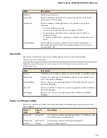
Page 61: ...Platform Guide i5000 i7000 i10000 i11000 Series 61...

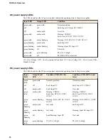
Page 62: ...Platform Specifications 62...

Page 63: ...d ship date These will be needed to track lost shipments Note Do not include any cables removable XFP SFP modules GBICs or other peripheral items if you are returning the platform to F5 Repackaging th...

Page 64: ...Repackaging Guidelines 64...

Page 65: ...y the coin battery is used only for system specific tasks No customer data is maintained by the battery backed volatile memory No further action is required by customers for equipment that includes vo...

Page 66: ...he HDD removal SKU you can remove the HDD SSD and coin battery and these components will be replaced during F5 reprocessing Otherwise HDD and SSD components are processed by F5 through standard proces...

Page 67: ...ts indicated at https f5 com about us policies patents Export Regulation Notice This product may include cryptographic software Under the Export Administration Act the United States government may con...

Page 68: ...complies with Canadian ICES 003 Standards Compliance This product conforms to the IEC European Union ANSI UL and Canadian CSA standards applicable to Information Technology products at the time of ma...

Page 69: ...ing 27 chassis locator LED enabling disabling 14 chassis power LEDs 15 chassis ventilation diagram 50 China material content listing See China RoHS Directive standards China RoHS Directive standards 6...

Page 70: ...a types 20 viewing valid media types using tmsh 21 J jumbo frames 53 L LCD about 8 about using 9 menu options 8 putting into menu mode 9 removing the protective film 29 using to configure the manageme...

Page 71: ...les and locking feature 28 connecting 28 power LEDs 15 power off on operation 11 power specifications for i11000 Series platforms 58 for i7000 Series platforms 57 i10000 Series platforms 57 i5000 Seri...

Page 72: ...rms 58 for power for i7000 Series platforms 57 for power supply 53 55 for processor 53 55 for solid state drive 53 55 for system features 53 power for i10000 Series platforms 57 power for i5000 Series...

Reviews: