


Rev A
110826
MSRD45.1
User Instruction Manual
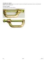
Locking Slide Bolt SRD Connector
This manual is intended to meet the Manufacturer's Instructions as required by the American National Standards
Institute (ANSI) Z359 and should be used as part of an employee training program as required by the Occupational
Safety and Health Act (OSHA).
WARNING
This product is part of a personal fall arrest, restraint, work positioning, suspension, or rescue system. A Personal Fall
Arrest System (PFAS) is typically composed of an anchorage and a Full Body Harness (FBH), with a connecting device,
i.e., a Shock Absorbing Lanyard (SAL), or a Self-Retracting Device (SRD), attached to the dorsal D-ring of the FBH.
These instructions must be provided to the worker using this equipment. The worker must read and understand the
manufacturer's instructions for each component or part of the complete system. Manufacturer's instructions must be
followed for proper use, care, and maintenance of this product. These instructions must be retained and be kept
available for the worker’s reference at all times. Alterations or misuse of this product, or failure to follow instructions,
may result in serious injury or death.
A Fall Protection Plan must be on file and available for review by all workers. It is the responsibility of the worker and
the purchaser of this equipment to assure that users of this equipment are properly trained in its use, maintenance,
and storage. Training must be repeated at regular intervals. Training must not subject the trainee to fall hazards.
Consult a doctor if there is reason to doubt your fitness to safely absorb the shock of a fall event. Age and fitness
seriously affect a worker’s ability to withstand falls. Pregnant women or minors must not use this equipment.
ANSI limits the weight of fall protection equipment users to a maximum of 310 lbs. Products in this manual may have a
rated capacity exceeding ANSI capacity limits. Heavy users experience more risk of serious injury or death due to falls
because of increased fall arrest forces placed on the user's body. In addition, the onset of suspension trauma after a fall
even may be accelerated for heavy users.
The user of the equipment discussed in this manual must read and understand the entire manual before beginning
work.
NOTE: For more information consult the ANSI Z359 body of standards.
FallTech
1306 South Alameda Street
Compton, CA 90221, USA
1-800-719-4619
1-323-752-0066
2016
©


