background image

092017

FK331

OPERATOR AND PARTS MANUAL

Snowblower

Model 7420, 8420, 8420G

Summary of Contents for Allied 8420G

Page 1: ...092017 FK331 OPERATOR AND PARTS MANUAL Snowblower Model 7420 8420 8420G...

Page 2: ......

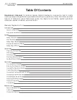
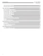
Page 3: ...LeavingThe Operator s Position 29 Tractor Requirements 29 ConnectingThe SnowblowerToTractor 30 ConnectingThe PTO Driveline 31 Connecting Hydraulic Hoses 35 Adjusting Skid Shoe Height 36 Theory Of Ope...

Page 4: ...box 84 Models 57 Three Point Hitch 74 Models 58 Three Point Hitch 84 Models 59 Hydraulic Spout Rotator 60 Hand Crank Spout Rotator 61 Hydraulic Spout Deflector Cylinder Hose Kit 62 PTO Shaft 63 PTO Ad...

Page 5: ...hainTension Checked Skid Shoes Properly Adjusted All Fasteners AreTight Lubricate Machine Hydraulic Hoses And FittingsTight If Applicable Safety Chain On Hitch All Decals Installed Guards And Shields...

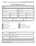
Page 6: ...Warranty Registration Form 7420 8420 8420G 2...

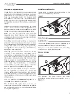
Page 7: ...equipment READ AND UNDERSTAND THIS OPERATOR AND PARTS MANUAL BEFORE OPERATING YOUR FARM KING EQUIPMENT If you have any questions see your Farm King dealer This manual may illustrate options and acces...

Page 8: ...Introduction 7420 8420 8420G 4...

Page 9: ...rranty or guarantee of any kind written or expressed implied or otherwise with regard to the information contained within this manual Farm King assumes no responsibility for any errors that may appear...

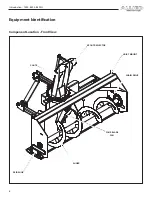
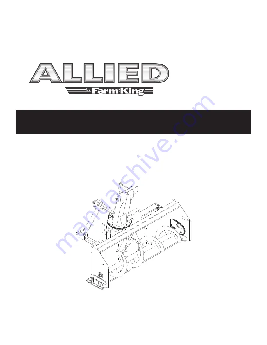
Page 10: ...Introduction 7420 8420 8420G 6 Equipment Identification Component Location Front View SKID SHOE AUGER FOUR BLADE FAN SPOUT DEFLECTOR CHUTE HOIST MOUNT CHAIN DRIVE...

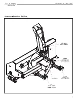
Page 11: ...Introduction 7420 8420 8420G 7 Component Location Top View HYDRAULIC MOTOR MOUNT PTO SHIELD LOWER THREE POINT MOUNTING PIN LOWER THREE POINT MOUNTING PIN UPPER THREE POINT MOUNTING PIN...

Page 12: ...Introduction 7420 8420 8420G 8...

Page 13: ...fety Rules 12 Safety Rules For PowerTake Off PTO Driven Equipment 12 Machine Requirements And Capabilities 13 Transport Safety 13 Fire Prevention 14 Maintenance 14 Operation 14 Starting 14 Electrical...

Page 14: ...Safety 7420 8420 8420G 10...

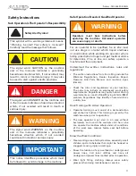
Page 15: ...r who is taking prescription drugs must get medical advice to determine if he or she can safely operate a machine and the equipment Understand the written instructions rules and regulations The writte...

Page 16: ...fety and could affect the life of the equipment Stop tractor engine place all controls in neutral set park brake remove ignition key and wait for all moving parts to stop before servicing adjusting re...

Page 17: ...blocks underneath and support the equipment securely before working under raised equipment Keep bystanders clear of moving parts and the work area Keep children away Use increased caution on slopes an...

Page 18: ...e section Do not use the machine where exhaust arcs sparks or hot components can contact flammable material explosive dust or gases Starting Do not use ether or starting fluids on any engine that has...

Page 19: ...ng or welding painted parts Wear dust mask when grinding painted parts Toxic dust or gas can be produced Dust generated from repairing nonmetallic parts such as hoods fenders or covers can be flammabl...

Page 20: ...431 Item 3 Figure 3 Safety Signs Decals Follow the instructions on all the signs decals that are on the equipment Replace any damaged signs decals and be sure they are in the correct locations Equipme...

Page 21: ...d Signs Check and replace any worn torn missing or hard to read decals on your equipment Figure 4 910823 Item 1 Figure 4 815397 Item 1 Figure 4 967388 Item 3 Figure 4 817585 Propeller Model Not Shown...

Page 22: ...and the Occupational Safety and Health Administration OSHA Anyone who will be operating and or maintaining the snowblower must read and clearly understand ALL Safety Operating and Maintenance informat...

Page 23: ...Assembly 7420 8420 8420G 19 Assembly Preparing For Assembly 21 PTO Shield 22 Hitch Assembly 22 Discharge Spout Deflector 24 Hydraulic Spout Deflector Option 25 Hydraulic Spout Rotator 26...

Page 24: ...Assembly 7420 8420 8420G 20...

Page 25: ...nd the equipment when backing up to the equipment for connecting Move the tractor snowblower and components to an area large enough for assembly WARNING AVOID INJURY OR DEATH Before you leave the oper...

Page 26: ...gure 7 with the inside brackets on the hitch tubes Attach each hitch arm with a 7 8 x 2 1 2 hex bolt and lock nut 2 1 3 3 PTO Shield Figure 5 7420 8420 Models Bolt the PTO shield Item 1 to the top of...

Page 27: ...m 3 Figure 9 with the hitch tubes Attach each hitch arm with a 7 8 x 5 hex bolt and lock nut 2 1 3 3 Figure 8 7420 Models Attach the top brackets of the left and right hitch arms Item 1 by bolting a l...

Page 28: ...ighten all hardware Attach a Category 1 top link pin Item 6 Figure 10 to the top front holes of the top brackets The Category 1 pin is used for a standard three point hitch only The bushing in the low...

Page 29: ...gure 13 Install the spout deflector Item 1 on the discharge spout Attach using one hinge pin Item 2 Figure 13 and retaining pins Align the spout deflector adjustment rod Item 3 on the mounts Attach us...

Page 30: ...with the gear hub facing downwards Align the gear with the toothed spout ring Attach the gear using one 1 4 x 3 4 bolt and 1 1 2 OD x 5 16 ID washer The spout opening should face forward The non tooth...

Page 31: ...rements 29 ConnectingThe SnowblowerToTractor 30 ConnectingThe PTO Driveline 31 PTO Driveline Length Check 32 PTO Driveline Bottoming Out Check 32 ReducingThe PTO Driveline Length 33 PTO Driveline Enga...

Page 32: ...Operation 7420 8420 8420G 28...

Page 33: ...d to check for leaks Note Do not operate with hydraulic leaks 6 Check that all electrical connections are tight 7 Check the augers Remove any twine wire or other material that has become entangled Ent...

Page 34: ...WARNING AVOID INJURY OR DEATH Before moving the tractor look in all directions and make sure no bystanders especially small children are in the work area Do not allow anyone between the tractor and th...

Page 35: ...driveline damage Do not modify the three point hitch Make sure the PTO driveline is of adequate length and that u joints are in the correct phase Remove the PTO driveline from the storage position if...

Page 36: ...ll rotating components are stopped before leaving the operator s position Do NOT service the tractor or implement with the PTO engaged Do NOT service the implement in a raised position unless properly...

Page 37: ...r the operator s position See Entering The Operator s Position in the Operation section Start the engine Raise or lower the three point implement to get the shortest distance between the tractor PTO s...

Page 38: ...line length by 1 667 to determine the PTO driveline Maximum Operating Length i e 25 5 in 647 7 mm x 1 667 42 5 in 1079 7 mm Maximum Operating Length 4 Attach the PTO driveline to the tractor PTO outpu...

Page 39: ...uplers on the tractor until they are fully engaged and locked WARNING HIGH PRESSURE FLUID HAZARD To prevent serious injury or death from high pressure fluid Relieve pressure on system before repairing...

Page 40: ...g the operator s position Place blocking under the snowblower Position blocking away from skid shoes allowing access to skid shoe mounting bolts and nuts Enter the operator s position See Entering The...

Page 41: ...p hands feet clothing and hair away from moving parts Stop engine set brake remove key and wait for all moving parts to stop before servicing adjusting repairing and unplugging Remove bystanders espec...

Page 42: ...to serious injury or death Tractor tow vehicle and hitch must have the rated capacity to tow equipment Verify that the tractor tow vehicle is approved for transporting the equipment and that the equi...

Page 43: ...39 Maintenance Service Schedule Chart 41 Lubrication 42 Recommendations 42 Locations 42 Oil Bath Gearbox 44 Chains And Fasteners 44 Safety Sign Decal Installation 45 Storage And ReturnTo Service 45 St...

Page 44: ...Maintenance 7420 8420 8420G 40...

Page 45: ...through this troubleshooting section please call your local distributor dealer or factory Before you call please have this Operator And Parts Manual and the serial number of your machine at hand Maint...

Page 46: ...perly grounded Use adequate light for the job Use only tools jacks and hoists of sufficient capacity for the job Replace and secure all shields removed during servicing before operating Use heavy leat...

Page 47: ...2 Figure 23 Grease every 10 20 hours Figure 24 Apply two pumps of grease to the slip clutch Item 1 Figure 24 and PTO quick disconnect Item 2 Figure 24 Grease every 10 20 hours Figure 25 Apply grease...

Page 48: ...ours Chains And Fasteners Periodically check all bolts and fasteners for tightness Figure 28 Check the main fan bolt Item 1 Figure 28 for tightness Check the tension in the drive chain Item 2 Figure 2...

Page 49: ...And ReturnTo Service Storage Sometimes it may be necessary to store your Farm King snowblower for an extended period of time Below is a list of items to perform before storage IMPORTANT DO NOT permit...

Page 50: ...t has been in storage it is necessary to follow a list of items to return the equipment to service Be sure all shields and guards are in place Lubricate the equipment Connect to a tractor and operate...

Page 51: ...Gearbox 49 Main Components Oil Bath Gearbox 53 Oil Bath Gearbox 84 Models 57 Three Point Hitch 74 Models 58 Three Point Hitch 84 Models 59 Hydraulic Spout Rotator 60 Hand Crank Spout Rotator 61 Hydrau...

Page 52: ...Parts Identification 7420 8420 8420G 48...

Page 53: ...r machine to assist them in ordering and obtaining the correct parts Use the exploded view and tabular listing of the area of interest to exactly identify the required part 11 10 1 42 16 32 3 41 20 14...

Page 54: ...Parts Identification 7420 8420 8420G 50 Main Components Open Gearbox 13 12 12 2 27 26 24 28 34 5 4 21 35 19 19 53 52 19 4 51 2 31 37 43 48 23 29 31 2 54 55 56 57 58 59 60 61 62 63 64...

Page 55: ...IVE SHAFT 1 16 81620 1 2 X 1 1 4 HEX BOLT PL 8 17 816255 74 84 PARKING STAND 1 18 816268 1 2 X 1 USABLE LENGTH DETENT PIN 1 19 81678 5 8 FLAT WASHER STD PL 4 20 968627 1 1 2 BRG W COLLAR 2 21 817162 S...

Page 56: ...1 46 965816 BEV GEAR 1 1 4 BORE 1 47 965817 BEV GEAR 1 1 2 BORE 1 48 965818 1 1 4 BEARING AEL206 104 RHP 1230 4 49 965821 3 8 X 3 8 X 1 3 4 KEY 1 50 965826 SHEAR SPROCKET 13T 50 1 1 4 BORE 1 51 965827...

Page 57: ...Parts Identification 7420 8420 8420G 53 Main Components Oil Bath Gearbox 40 10 9 1 1 9 10 31 29 2 20 6 15 36 30 30 30 28 14 35 29 2 37 8 34 38 42 45 41 44 13 16 13 16 5 39 23 43 32 17...

Page 58: ...Parts Identification 7420 8420 8420G 54 Main Components Oil Bath Gearbox 24 25 12 11 11 2 22 21 27 29 2 37 33 17 17 7 18 17 3 32 4 3 19 45 41 2 29 35 26 46 47 48 49 50 51 53 52 54 55 56...

Page 59: ...FLAT WASHER STD PL 4 18 965844 IDLER SPRKT 15T 50 1 19 817162 SB CAST SKID SHOE 2 20 817454 GUARD DRIVESHAFT 84 1 21 818134 PLATE FAN SHIELD 1 22 818280 SPACER BOTTOM SPOUT ROTATION 1 23 818678 WELDM...

Page 60: ...1 4 FAN SHFT KEY 1 45 965818 1 1 4 Bearing AEL206 104 RHP 1230 3 46 812026 5 16 X 1 HEX BOLT PL 4 47 812362 5 16 LOCK NUT PL 4 48 81546 5 16 FLAT WASHER PL 4 49 818295 74 84 SPOUT GEAR RING 1 50 81828...

Page 61: ...SHAFT 7 BU50502 PINION SHAFT 8 BU50329 BEVEL GEAR 1 1 2 BORE 9 BU50331 BEVEL GEAR 1 3 8 BORE 10 BU50428 STAKING LOCK NUT 11 BU50444 STAKING LOCK NUT 12 BU50422 1 OIL SEAL 3 USED 13 BU50415 RETAINER R...

Page 62: ...LEVIS PIN 0 88 DIA X 3 3 4 LG 2 5 812365 3 4 LOCK NUT PL 3 6 84050 3 4 FLAT WASHER PL 3 7 84336 3 4 X 4 HEX BOLT PL 3 8 907213 BTMTUBE WELDT 2 9 907217 3 16 W X 2 X 2 X 22 UPR HTCHTUBE CAT 1 HTCH 1 10...

Page 63: ...PL 3 5 907220 3 16 W X 2 X 2 X 21 UPR HTCHTUBE CAT 1 2 1 6 907250 HTCHTUBE 3 16 X 2 1 2 X 2 1 2 X 20 5 8 2 7 907315 HITCH PIN 88 X 4 25 SB CAT 1 2 2 8 907316 PIN SLEEVE 7 64 W X 1 1 8 X 2 7 8 2 9 907...

Page 64: ...3 817014 PINION GEAR 14TEETH 1 4 818903 ASSEMBLY MOTOR MANIFOLD 1 5 907590 SPT HOSE HLDR WELDT 1 6 812026 5 16 X 1 HEX BOLT PL 4 7 812362 5 16 LOCK NUT PL 4 8 812623 WASHER 5 16 SAE FLAT PL 4 9 813748...

Page 65: ...X 2 00 GR5 PL 1 4 81570 3 8 STD FLAT WASH PL 17 5 816893 HORTIZONAL BRACE 1 6 816894 VERTICAL BRACE 1 7 816895 CRANK BRACKET 1 8 816896 CRANK HANDLE 12GA X 1 0 1 9 816897 GEAR WELDMENT 1 10 816993 HAN...

Page 66: ...PART NUMBER DESCRIPTION 24930M 1 3 4 ID X 5 STROKE CYLINDER 116983 HOSE 3 8 X 120 C W FITTINGS 960913 CLEVIS PIN 1 2 X 1 8125 PL 9812430 COTTER PIN 1 8 X 1 00 PL 811918 ELBOW 90 9 16 SWMORB X 9 16 MJ...

Page 67: ...OKE W TUBE SLEEVE 3 925293 CROSS KIT W GREASE NIPPLE 4 817774 CHAIN 5 817807 SHAFT SHIELD 6 817808 RETAINER 7 817809 RETAINER 8 818270 SHEAR BOLT CLUTCH 9 925305 INBOUNDYOKE INNERTUBE 10 818268 SPLINE...

Page 68: ...1 2 812624 1 4 FLAT WASHER PL 2 3 81523 1 4 X 1 2 HEX BOLT PL 2 4 81627 1 2 X 3 HEX BOLT PL 1 5 84498 1 4 LOCK NUT PL 2 6 960135 PTO SHLD SPRG 661 1 7 965821 3 8 X 3 8 X 1 3 4 KEY 1 8 9812433 3 16 X...

Page 69: ...fications And Shipping Kit Numbers 7420 8420 8420G 65 Specifications And Shipping Kit Numbers Specifications 67 Shipping Kit And Bundle Numbers 67 HardwareTorque Values 68 Metric Chart 68 Imperial Cha...

Page 70: ...Specifications And Shipping Kit Numbers 7420 8420 8420G 66...

Page 71: ...ng Kit And Bundle Numbers The following is a list of Kit Numbers for this product and the Bundle Numbers Descriptions and Quantities for each Kit Qty Bundle Description YC7420 4 74 Allied Snowblower 4...

Page 72: ...Specifications And Shipping Kit Numbers 7420 8420 8420G 68 HardwareTorque Values Metric Chart...

Page 73: ...Specifications And Shipping Kit Numbers 7420 8420 8420G 69 Imperial Chart...

Page 74: ...Specifications And Shipping Kit Numbers 7420 8420 8420G 70...

Page 75: ...71 Warranty Farm King Base Limited Warranty 73 Repair Parts Limited Warranty 73 What Is Not Covered 73 Authorized Dealer And Labor Costs 73 Warranty Requirements 74 EXCLUSIVE EFFECT OF WARRANTY AND LI...

Page 76: ...Warranty 7420 8420 8420G 72...

Page 77: ...n of the Farm King LimitedWarranty and used and serviced as provided for in the Operator s Manual to be free from defects in materials or workmanship for a period of thirty 30 days from the invoice da...

Page 78: ...NOT LIMITATION LOSS OF CROPS LOSS OF PROFITS OR REVENUE OTHER COMMERCIAL LOSSES INCONVENIENCE OR COST OF REPLACEMENT OF RENTAL EQUIPMENT IN NO EVENT SHALL FARM KING S CONTRACT OR WARRANTY LIABILITY E...

Page 79: ......

Page 80: ...on of Buhler Industries Inc 1330 43rd Street North Fargo ND 58102 Toll Free 888 524 1004 E mail info buhler com www farm king com Equipment shown is subject to change without notice 2017 BuhlerTrading...

Reviews: