This Quick Start Guide is intended for experienced installing technicians. It is a basic reference to ensure all connections are properly made.
Models include Delta3, Delta5, Delta5.3, Delta6.2, Delta6.4, Delta403, Delta405, Delta410, as well as variants supporting most industry lead-
ing card and tag technologies. For additional information please reference Farpointe Data’s website www.farpointedata.com.
1.0 Introduction
A key component of a physical security electronic access control
system, a contactless smartcard card reader is based on RFID
technology. In operation it is capable of reading data stored on a
proximity credential via radio frequency and without physical contact,
and then passing the data obtained to the physical access control
system. Access control systems typically manage and record the
movement of individuals through a protected area, such as a
locked door.
2.0 Mounting Provisions
Each reader may be installed either indoors or outdoors.Mounting
options shown in the table below. Use supplied #6 mounting screws,
or equivalent security screws, for installation. Delta 400 Series
readers are supplied with #6 tamperproof screws.
Models
Mullion
Mount
Single-
Gang Wall
Mount*
Double-
Gang Wall
Mount*
European/
Asian Wall
Mount*
Delta3
•
Delta5
•
Delta5.3
•
Delta6.2
•
Delta6.4
•
Delta403
•
Delta405
•
Delta410
•
*Plastic or metal
3.0 Reader Wiring
Wiegand
Magstripe
Conductor
Function
Conductor
Function
Red
DC (8-14 VDC)
Red
DC (8-14 VDC)
Black
Ground
Black
Ground
Green
Data 0
Green
Clock
White
Data 1
White
Data
Brown
Red LED
a
Brown
Red LED
Orange
Green LED
b
Orange
Green LED
Yellow
Card Present
Yellow
Card Present
Blue
Beeper
Blue
Beeper
Violet
Read Mode
Violet
Read Mode
Drain
Shield Ground
Drain
Shield Ground
4.0 Cable Requirements
24 AWG minimum, multi-conductor stranded with an overall foil shield,
for example Belden 9535 or similar, supporting the five conductors
comprising the physical layer of the Wiegand interface (power, ground,
data 0, data 1, and/or beeper and LED). Alternatively, Belden 9539 or
similar, for all reader functions. Contact your access control system
manufacturer for their specific requirements. Per the SIA’s Wiegand
specification, maximum cable length is 500 feet (152 m).
5.0 Output Formats
• Wiegand (industry standard 26-bit Wiegand
and custom Wiegand formats)
• Magnetic Stripe (ABA Track II, clock and data,
with card present)
6.0 Grounding
Shield (drain) continuity must run from the reader to the access panel.
Shield (drain) and reader ground must be tied together at the access
panel and connect to an earth ground at one point.
7.0 Power
Reader may be powered by the access panel. A linear power supply is
recommended for best operation.
8.0 Voltage and Current
Voltage: 8 to 14 VDC
Current Draw: 135mA typical at 12 VDC
9.0 Read Mode
For sector (access control) reads, pull the purple conductor low.
10.0 Connection
Connection must be done in accordance with NFPA 70. Do not
connect to a receptacle controlled by a switch. Connect to a power
limited DC voltage source.
QUICK START GUIDE
13.56-MHz CONTACTLESS
SMARTCARD READERS
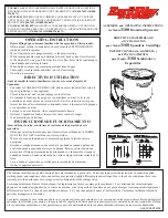
WIRING NOTES:
a
Single Line LED:
This is the standard operating mode and does not make use of the
Orange conductor. The LED is Red when the reader is idle and flashes when a card is
presented. The LED turns Green when the Brown Conductor is pulled low by the access
control panel.
b
Dual Line LED:
This mode makes use of both the Brown and Orange conductors. The
Brown conductor controls the Red LED and the Orange conductor controls the Green
LED. LED states are determined by the access control system option and capability.
Unused conductors should be trimmed, isolated and taped back to prevent unintended
current flows. Apply positive voltage only to the Red DC Conductor.