background image

Versione 1.0  M a g g i o   2019 

Manuale Uso e Manutenzione 


IT 

SMONTAGOMME : 
TYRE CHANGER : 

RA

S

E.2247


Instruction Manual 

UK 


Version 1.0  M a y  2019 

FASEP 2000s.r.l. Via Faentina 96 - 50032 Borgo San Lorenzo (Fi) - ITALY

Tel. +39 055 8403126 - Fax +39 055 2691906

info@fasep.it - www.fasep

Summary of Contents for RASE.2247

Page 1: ...le Uso e Manutenzione IT SMONTAGOMME TYRE CHANGER RASE 2247 Instruction Manual UK Version 1 0 May 2019 FASEP 2000s r l Via Faentina 96 50032 Borgo San Lorenzo Fi ITALY Tel 39 055 8403126 Fax 39 055 26...

Page 2: ...IZIONE 9 DATI TARGA D IDENTIFICAZIONE 9 DATI TECNICI 10 ACCESSORI IN DOTAZIONE 11 ACCESSORI A RICHIESTA 11 CONDIZIONI D UTILIZZAZIONE PREVISTE 11 PRINCIPALI ELEMENTI DI FUNZIONAMENTO 12 DECALCOMANIE 1...

Page 3: ...cchiatura tutta la documentazione dovr esservi allegata Il manuale da ritenersi valido esclusivamente per il modello e la matricola rilevabili dalla targhetta applicata su di esso ATTENZIONE Attenersi...

Page 4: ...ZIONE Per evitare danneggiamenti non sovrapporre atri colli sull imballo Dimensioni imballo S 40 1 Larghezza 765 mm Profondit 980 mm Altezza 970 mm Peso macchina con imballo S 40 1 versione standard 0...

Page 5: ...o operante in posizione abbassata Svitare la vite V1 e dado D1 presente sulla forcella F per cilindro e con l aiuto di un muletto sollevare il palo di lavoro per posizionarlo sulla colonna macchina co...

Page 6: ...e necessario osservare le norme vigenti di sicurezza sul lavoro IMPORTANTE per un corretto e sicuro utilizzo dell attrezzatura si raccomanda un valore di illuminazione dell ambiente di almeno 300 lux...

Page 7: ...e manuale Per evitare l uso della macchina da parte di personale non autorizzato si consiglia di disconnettere la spina di alimentazione quando questa rimane inutilizzata spenta per lunghi periodi ATT...

Page 8: ...ante il lavoro potrebbero inserirsi tra parti in movimento della macchina 7 Non toccare linee o l interno di motori e apparecchiature elettriche senza prima assicurarsi che sia stata tolta corrente 8...

Page 9: ...me automatico a funzionamento elettrico pneumatico opera su ruote intere a canale con pesi e dimensioni indicate nel paragrafo dati tecnici Progettato per operare correttamente su 1 Ruote convenzional...

Page 10: ...ivelli di emissione e non rappresentano necessariamente livelli operativi sicuri Nonostante esista una relazione fra livelli di emissione e livelli di esposizione questa non pu essere utilizzata in mo...

Page 11: ...ONDIZIONI DI UTILIZZAZIONE PREVISTE ATTENZIONE Ogni altro utilizzo diverso da quello descritto da considerarsi improprio ed irragionevole Le macchine sono dotate di un sistema di gonfi aggio indipende...

Page 12: ...retto e sottoposta a periodica manutenzione I principali elementi di funzionamento della macchina sono rappresentati in fig 7 8 1 Pedale invertitore 2 Piatto autocentrante 3 Pedale controllo stallonat...

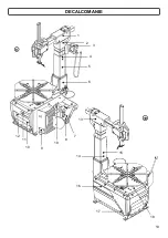
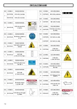
Page 13: ...DECALCOMANIE 9 10 13 1 2 3 4 13 18 14 15 9 19 8 5 6 10 11 12 16 17 7...

Page 14: ...iare per RIF CODICE DESCRIZIONE 7 30015042 Etichetta schiacciamento RIF CODICE DESCRIZIONE 13 30015055 Etichetta modello 30015057 Etichetta modello RIF CODICE DESCRIZIONE 2 30015039 Etichetta pericolo...

Page 15: ...etamente Ripetere l operazione sul lato opposto della ruota 11 a STALLONATURA PNEUMATICA Chiudere completamente le griffe dell autocentrante agendo sul pedale 5 fig 7 Toglere tutti i pesi di bilancia...

Page 16: ...lle griffe rappresentando un potenziale rischio di cesoia mento per le mani Durante il bloccaggio del cerchione non tenere le mani sotto il pneumatico 12 16 Posizionamento dell utensile Riportare in p...

Page 17: ...loro assemblaggio Verificare inoltre che i cerchi non abbiano subito deformazioni non presentino i fori di fissaggio ovalizzati incrostati o arrugginiti e non vi siano bave taglienti sul foro della v...

Page 18: ...dere se vengono gonfiati oltre questi limiti o possono danneggiarsi gravemente nelle strutture in modo non visibile sul momento TENERE LE MANI E TUTTO IL CORPO LONTANI DAL PNEUMATICO DURANTE IL GONFIA...

Page 19: ...e di massima o del limitatore di pressione Il costruttore declina ogni responsabilit per i danni causati dalla manomissione di suddette valvole AVVERTENZA In caso di sostituzione del cavo di alimentaz...

Page 20: ...viti di scorrimento Controllare il livello dell olio nel lubrificatore aria e se necessario rabboccare con olio non detergente SAE20 fino al livello L1 indicato in fig 19 Pulire con panno asciutto Evi...

Page 21: ...e organizzano opportuni sistemi di raccolta e smaltimento delle apparecchiature stesse Alla fine della vita del prodotto rivolgetevi al vostro distributore per avere informazioni sulle modalit di racc...

Page 22: ...otettivi in caso di schizzi Olio minerale indicazioni di pronto soccorso Ingestione rivolgersi al presidio medico con le caratteristiche del tipo di olio ingerito Inalazione in caso di esposizione a f...

Page 23: ...pedale rotta Sostituire molla richiamo pedale Manca olio nel lubrificatore Rabboccare con olio SAE20 non detergente nel lubrificatore PERDE ARIA ALL INTERNO Perde aria dal rubinetto dalla parte del r...

Page 24: ...dosi al rivenditore Cilindro discesa difettoso Sostituire cilindro I BLOCCAGGI VERTICALE E ORIZZONTALE NON FUNZIONANO Non passa aria dalla maniglia Verificare integrit tubi Sostituire maniglia rivolge...

Page 25: ...ON 9 MANUFACTURER S LABEL 9 TECHNICAL DATA 10 STANDARD ACCESSORIES 11 ACCESSORIES SUPPLIED ON DEMAND 11 SPECIFIED CONDITION OF USE 11 MAIN OPERATING PARTS 12 WARNING SIGNALS 13 USE 15 DEMONTAGE 16 MON...

Page 26: ...is only to be considered valid for the model with the serial number indicated on the na meplate applied to it WARNING Observe the contents of this manual the producer declines all liability in the cas...

Page 27: ...for machine hoisting WARNING Do not stack other goods on top of the packing to avoid damaging it Packing dimensions S 40 1 Width 765 mm Depth 980 mm Height 970 mm Weight of the machine with packing S...

Page 28: ...arm in a lowered position with a hand Unscrew the screw V1 and the nut D1 on the fork F on each cylinder and with the help of a forklift lift the working pole to position it on the machine column At t...

Page 29: ...ANT for correct safe use of the equipment users must ensure a lighting level of at least 300 lux in the place of use CAUTION The installation of the machine must be performed in a dry area which must...

Page 30: ...g diagram in this manual In order to prevent the machine from being used by unauthorized personnel it is advisable to di sconnect the power supply plug when the machine remains idle switched off for l...

Page 31: ...relevant regula tions and legislation 6 Never leave nuts bolts tools or any other equipment on the tyre changer as they may become entrapped between moving parts 7 Do not touch power lines or the ins...

Page 32: ...umatic automatic tire changer to be used with wheels with drop center featuring weight and dimensions as described in the technical data section It is engineered to work effectively on 1 Conventional...

Page 33: ...d correspond to emission levels and do not necessarily represent safe ope rating levels Although there is relationship between emission levels and exposure levels this can not be used reliably to esta...

Page 34: ...l hub kit Pneumatic wheel lift USE CONDITIONS WARNING Any other use other than that described is to be considered improper and un reasonable The machines are equipped with an inflation system independ...

Page 35: ...e must be installed and operated correctly and serviced regularly The machine main operating parts are shown in 7 8 1 Reverse control pedal 2 Turntable 3 Bead breaker pedal 4 Bead breaker arm 5 Clamp...

Page 36: ...LABELS 13 9 10 1 2 3 4 13 18 14 15 9 19 8 5 6 10 11 12 16 17 7...

Page 37: ...IONE 7 30015042 Legs crushing danger label RIF CODICE DESCRIZIONE 13 30015055 Model machine label LT gray 30015057 Model machine label LT White RIF CODICE DESCRIZIONE 2 30015039 Exploding danger label...

Page 38: ...nts to free it completely Repeat this ope ration on the other side of the wheel 11 a PNEUMATIC BEAD BREAKING Fully close the turntable clamps acting on pedal 5 fig 7 Remove the weights on the rim Full...

Page 39: ...e pedal 5 fig 7 closes the clamps and may be dangerous danger of hands crushing While rim clamping do not keep the hands under the tire 12 16 Tool positioning Bring the working arm in working position...

Page 40: ...unting Also check that rims are not deformed that their fixing holes have not become oval that they are not scaled or rusty and that they do not have sharp burrs on the valve holes Be sure that the ti...

Page 41: ...eyond these limits or their structures may incur se rious damage not visible at the time KEEP YOUR HANDS AND THE WHOLE BODY WELL AWAY FROM THE TYRE DURING INFLATION Make sure you are concentrated duri...

Page 42: ...re limiter is forbidden The manufacturer declines all liability for damage resulting from tampering with the se valves CAUTION In case of replacement of the power supply cable follow the indications l...

Page 43: ...relevant sliding screws Check the oil level in the air lubricator and if necessary top up with non detergent SAE20 oil to the indicated level L1 see fig 28 Clean with a dry cloth Avoid contact with so...

Page 44: ...alers set up proper collection and treatment systems for these products At the end of life of your product contact your dealer to have information on the collection arrange ments A disposal of the pro...

Page 45: ...protect against oil splashes Mineral oil first aid procedures Swallowing seek medical attention providing the characteristics of the type of oil swallowed Inhalation in case of exposure to high concen...

Page 46: ...LE TOP PEDAL DO NOT RETURN TO HOME POSITION Control spring broken Renew the spring No oil in lubricator Top up lubricator with SAE20 non detergent oil AIR LEACK INSIDE THE MACHINE Air leak from bead b...

Page 47: ...L WITH DIFFICULTY Insufficient belt tension Adjust tension or replace belt THE TYRE PRESSURE GAUGE NEEDLE FAILS TO RETURN TO 0 Pressure gauge faulty or damaged Replace pressure gauge WARNING The Spare...

Page 48: ...SCHEMA ELETTRICO ELECTRIC SCHEME 25 S 40 1 P...

Page 49: ...26 SCHEMA ELETTRICO ELECTRIC SCHEME S 40 1 P...

Page 50: ...SCHEMA ELETTRICO ELECTRIC SCHEME S 40 1 E 27...

Page 51: ...SCHEMA ELETTRICO ELECTRIC SCHEME S 40 1 E 28...

Page 52: ...RATOR AND PRESSURE REG LUBRIF 9 CILINDRO ROTAZIONE PALO VERTIVAL POST CYLINDER 10 VALVOLA DISTRIBUTORE DISTRIBUTION VALVE 11 RACCORDO GIREVOLE ROTATING UNION 12 CILINDRO AUTOCENTRANTE SELF CENTERING C...

Page 53: ...ILINDRO PRESSORI PRESS SYSTEM CYLINDER 7 VALVOLA COMANDO PRESSORI HELPING ARMS CONTROL VALVE 8 GRUPPO LUBRIFICATORE WATER SEPARATOR AND PRESSURE REG LUBRIF 9 CILINDRO ROTAZIONE PALO VERTIVAL POST CYLI...

Reviews: