140903 FBs-CMGSM User's Manual EN v3-04
Page #
1 of 7
FBs-CMGSM
User’s Manual
1.
Introduction
FBs-CMGSM
(
CMGSM
for short) is communication module for FATEK PLC systems
FBs-xxMC.
CMGSM
uses the GSM network to transfer the data.
CMGSM
is based
on the quad band GSM module
(850/900/1800/1900 MHz). CMGSM
is backed
up by Li-Ion accumulator.
CMGSM offer three different ways of communication with connected PLC.
The first one is
monitoring and remote control of PLC via SMS. CMGSM
reads
periodically PLC registers containing a flag to send SMS, if the flag is set,
CMGSM
reads destination phone number and string of characters (text), sends SMS and
clears the flag. If there is a SMS received by CMGSM, it is written into PLC registers
including another flag “SMS received” to be processed by PLC program. At the end
the PLC program clears this flag. So these operational SMS must be processed by
PLC program both on SMS reception and SMS sending. Some status and event SMS
are predefined in CMGSM (e.g. “Connection to PLC failure”) and only the destination
phone number have to be set in PLC registers.
The second way of communication with PLC via CMGSM is
dial up data transfer
via GSM network (CSD).
The connection can be only incoming for CMGSM, that
may be initiated from a control center for the purpose of remote system analysis
and PLC software tuning and modification by WinProladder SW.
The third way of CMGSM communication over the GSM network is
GPRS data
connection
using TCP/IP protocol. CMGSM opens the connection in
TCP client
mode.
Any SIM card, that can provide internet connection over the GSM network,
can be used. CMGSM connects to IP address and port specified in from PLC. It is
important to notice, that the connection can be opened in direction from CMGSM to
PC (server) only. PC cannot open a connection to CMGSM because CMGSM has no
server implemented and usually does not have public IP address. GPRS has special
data transfer properties (data grouping, data transfer delay 1 ... 10 seconds), which
are not suitable for WinProladder SW.
WinProladder must use dial up data
transfer (so called CSD) only.
Main features
Three ways of GSM network use – SMS, GPRS, Data Call CSD (all of
them practically at the same time)
WinProladder remote GSM dial up data transfer connection (CSD)
USB port for module monitoring
One digital input IN and one digital output OUT
Firmware update via GSM available
Li-Ion backup accumulator – min. 2 days of operation w/o charging
Lowest level super watchdog function (Hardware Power OFF)
FBs-CMGSM can be used directly with PLC FBs-xxMC (Port 3)
SMS functionality is fully under PLC program control
Configuration of CMGSM means just to set several PLC registers
No PLC program support is necessary for CSD and GPRS operation
LEDs for indication of the CMGSM status and data flow signalization
Unlimited number of logical and analog inputs and outputs can work
with one CMGSM (PLC network)
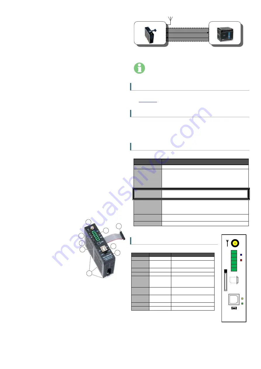
1)
GSM antenna connector
2)
IO connector
3)
SIM card holder
4)
USB connector
5)
DIN rail holder
6)
FUNC button
7)
Indication LEDs Rx, Tx
8)
Flat cable for connection to PLC
9)
Indication LEDs GSM, ERR
2.
Content of the
Delivery
1 pc of
FBS-CMGSM
1 pc of antenna GSM-ANT05S
1 pc of 6 pin connector, pitch 3.81 mm
1 pc of CD with documentation
3.
Typical Application, Installation
FATEK PLC
CMGSM
Power + 5 V
DC
GSM
Antenna
RS 232 Communication
Flat cable
Note: FATEK PLC is not part of the delivery of this product. It is needed to order
independently.
Warning
Turn off all power supply during installation of
CMGSM
to PLC to
prevent damage to equipment!
3.1
Configuration
If a SIM card does not need PIN code, no configuration for basic use is necessary.
For the SIM card with PIN code the configuration in PLC is necessary. Read chapter
for more.
3.2
Hardware settings
Switch off the power supply of PLC
Connect GSM antenna
Insert SIM card
Connect the flat cable between CMGSM and PLC
3.3
Startup
Device status is indicated with blue GSM LED on the CMGSM front panel. Valid
statuses are as follows:
Term
Description
permanently off
No power or STAND BY mode.
600 ms on /
600 ms off
Device is not logged into the GSM network.
This state occurs after start of device for approx. 30 seconds.
If it remains, check: SIM card (is inserted?, is valid?)
Antenna (is connected?)
Configuration (is SIM PIN correct?)
75 ms on /
3 s off
Device is logged into the GSM network and is idle. (It means
that no GPRS nor CSD connection is active.)
75 ms on /
75 ms off /
75 ms on /
3 s off
GPRS active, no data
500 ms on /
50 ms off
GPRS active, data transfer in progress
permanently on
CSD (data connection) in progress
Expressed line is common operating state.
3.4
Front Panel
Name
Element
Description
ANT
Connector
GSM Antenna connector
GSM
LED blue
GSM status
(see the previous table)
ERR
LED red
Error
IO
Connector
IN (input), OUT (output)
FUNC
Button
Multifunction Button:
DOUT2 change, RESTART,
STAND BY mode.
SIM
CARD
SIM card
Holder
Press the SIM card to
remove it from holder
USB
Connector
USB connection to PC for
debugging purposes
RCV
LED yellow
Receiving SMS
SND
LED green
Sending SMS
3.4.1
Pushbutton “FUNC”
Pushbutton “
FUNC
” has several functions. Short press
changes the state of the output OUT (DOUT2). Long press (longer than 3 seconds)
will either
RESTART
CMGSM (if CMGSM is powered by the PLC) or enter the
STAND BY MODE
(if the CMGSM is powered from the internal accumulator - PLC is
either disconnected or turned off).
5
9
2
4
6
7
8
3
1
FBs-CMGSM
USB
COMMUNICATION
GSM MODULE
1
1
FUNC
RCV
SND
GSM
+
ERR
-
IN
OUT
SIM
PLC1.ir


