

Instruction manual
Instruction manual
Operating & Maintenance
Operating & Maintenance
4812274432.pdf
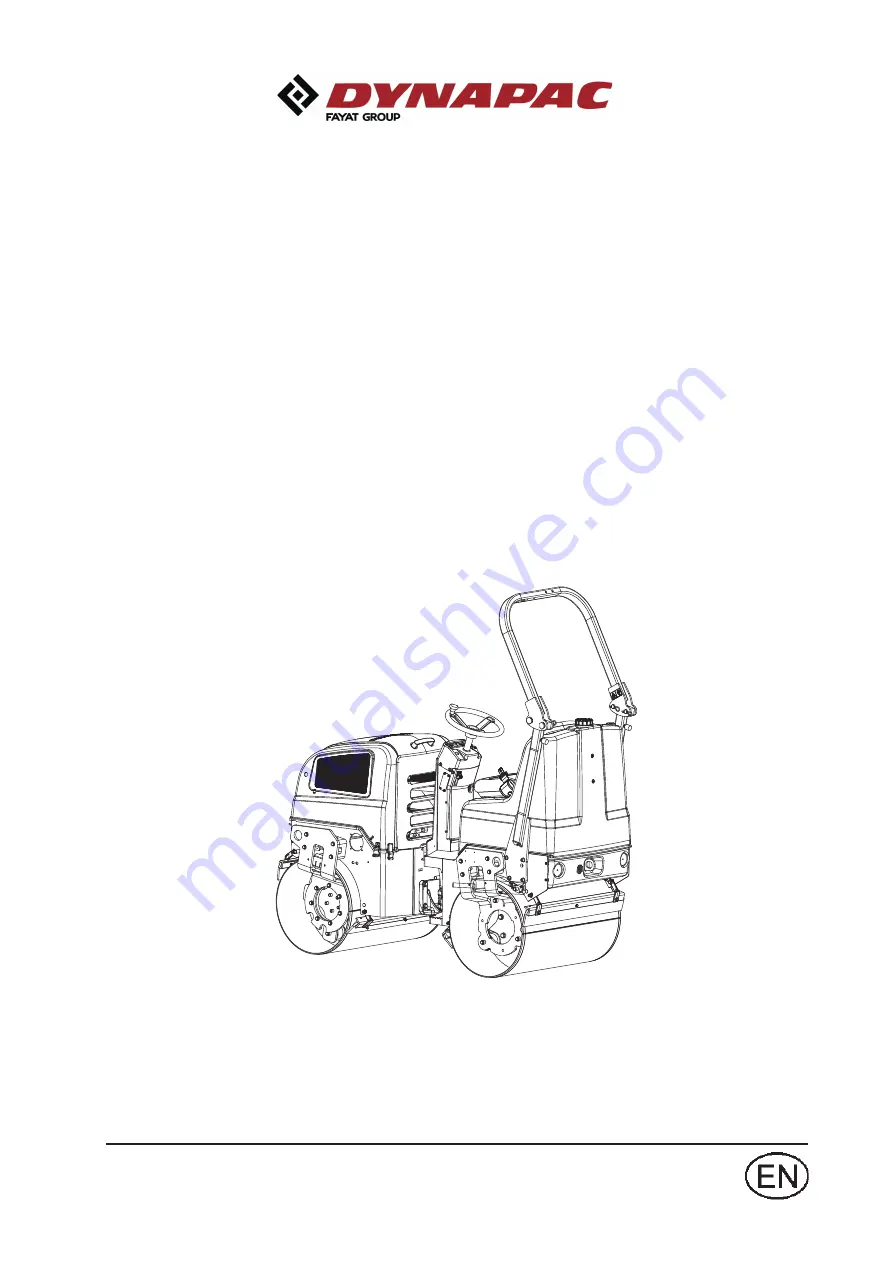
Vibratory roller
Vibratory roller
CC900G
CC900G
Engine
Engine
Honda GX630R
Honda GX630R
Serial number
Serial number
10000303x0C003469 - 0C005137
Translation of original instruction
Translation of original instruction
Reservation for changes
Reservation for changes
Printed in China
4812274432.pdf
Printed in China
10000303x0C005138 (Improved Frame) -
Summary of Contents for Dynapac CC900G
Page 2: ......
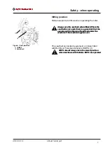
Page 16: ...Safety when operating 8 4812274432 pdf 2017 07 10 ...
Page 20: ...Special instructions 12 4812274432 pdf 2017 07 10 ...
Page 22: ...Technical specifications Noise Vibrations Electrical 14 4812274432 pdf 2017 07 10 ...
Page 30: ...Machine description Decals 22 4812274432 pdf 2017 07 10 ...
Page 42: ...Operation 34 4812274432 pdf 2017 07 10 ...
Page 54: ...Operating instructions Summary 46 4812274432 pdf 2017 07 10 ...
Page 56: ...Operating instructions Summary 48 4812274432 pdf 2017 07 10 ...
Page 58: ...Preventive maintenance 50 4812274432 pdf 2017 07 10 ...
Page 62: ...Maintenance Lubricants and symbols 54 4812274432 pdf 2017 07 10 ...
Page 70: ...Maintenance Maintenance measures before use 62 4812274432 pdf 2017 07 10 ...
Page 80: ...Maintenance 100h 72 4812274432 pdf 2017 07 10 ...
Page 88: ...Maintenance 500h 80 4812274432 pdf 2017 07 10 ...
Page 96: ...Maintenance 1000h 88 4812274432 pdf 2017 07 10 ...


