background image


- 1 - 

E2660                         

Revised 3/26/10 


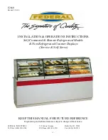
INSTALLATION & OPERATIONS INSTRUCTIONS 

Self-Contained & Remote Refrigerated Models 

& Non-Refrigerated Counter Displays  

(Service & Self-Serve) 


KEEP THIS MANUAL FOR FUTURE REFERENCE 

Engineering and technical data are subject to change without notice.


FEDERAL INDUSTRIES  


215 Federal Avenue 


Belleville, WI  53508 

Toll Free 1(800) 356-4206  


WI Phone (608) 424-3331  

Fax: (608) 424-3234 

Summary of Contents for CRR4828

Page 1: ...ated Models Non Refrigerated Counter Displays Service Self Serve KEEP THIS MANUAL FOR FUTURE REFERENCE Engineering and technical data are subject to change without notice FEDERAL INDUSTRIES 215 Federa...

Page 2: ...igeration Lines 12 Refrigeration Installation Refrigerated units 13 Self Contained Models 13 Remote Models 13 Case Line Up Installation 14 Top Joining Bracket 14 Bottom Pedestal Joining 15 END PANEL I...

Page 3: ...ons of this manual covering components contain technical instructions intended only for persons qualified to perform electrical work DANGER Improper or faulty hookup of electrical components in the ca...

Page 4: ...r death will occur if you ignore the message WARNING Severe injury or death can occur if you ignore the message CAUTION Minor injury or damage to your case can occur if you ignore the message NOTICE T...

Page 5: ...ord is factory installed protruding from the bottom rear corner of the case see the Cord Options section of this manual that pertains to your model case for alternate location If factory installed cor...

Page 6: ...s to be drilled through the counter top surface to attach case to counter Use the diagram below for hole placement location IMPORTANT When placing cases in a line up the number of end panels used will...

Page 7: ...ounter and counter must be fastened to floor IMPORTANT The condenser air inlet and discharge louvers are located in the rear of the case Do not block these louvers and do not locate them near a source...

Page 8: ...s in the control panel Disconnect power cord connections and move cord and cord strain relief from bottom hole in frame channel to the 7 8 hole in the control panel Reconnect power cord and plug botto...

Page 9: ...ing from the bottom rear corner of the base and will fall through the required cut in counter After the case has been installed and fastened onto the counter plug cord into a proper power source CORD...

Page 10: ...43 0 48 UNIT FRONT 22 62 3 0 29 0 2 1 2 HOLE REFRIGERATION AND EVAPORATOR CONDENSATE DRAIN CUSTOMER SIDE CORD OPTIONS CORD OPTION 1 The electrical cord is shipped from the factory protruding from the...

Page 11: ...MPORTANT When placing cases in a line up the number of end panels used will be different The cut out and hole placement dimension will need to be adjusted for each particular line up circumstance See...

Page 12: ...d cord strain relief from the bottom hole in the frame channel to the hole in the control panel and reconnect power cord Plug bottom hole in frame channel with the 7 8 hole plug removed from the contr...

Page 13: ...on lines from the condensing unit to the cabinet Horizontal suction lines should be pitched downward towards the condensing unit at least per 10 run to aid the oil drainage A P trap must be installed...

Page 14: ...d panel when being butted up to a case with an end panel Remove them from case and discard Once the cases are placed together with proper end panel s They will need to be pushed together as close as p...

Page 15: ...s 1 Clean the front corner area on pedestal with rubbing alcohol 2 Remove adhesive backing strips from pedestal joining plate 3 Center plate over opening and press firmly into place The rear plate mus...

Page 16: ...a line up the number of end panels and end panel type will be different for each line up circumstance See Case Line Up Installation section of this manual 1 Place end panel on to the side of case and...

Page 17: ...e to the end glass These steps may have already been performed at the factory for you Insert a longer bottom shelf bracket in the desired shelf standard slot on one side of case bumper side towards en...

Page 18: ...k Install door labeled inner door first on inner track and door labeled outer door second on outer track Shelves and shelf light quantity It is not required that all shelves and shelf lights supplied...

Page 19: ...to set on This step may have already been performed at the factory for you NOTE Clean area of glass where glass shelf holder is to be located with rubbing alcohol and let air dry before installing sh...

Page 20: ...OWER TRACK 1 Start with the outer outside door and lift the door upward until the bottom edge of door clears the lower track and then swing the bottom of the door outward and down out of upper track 2...

Page 21: ...ting circuit and to the optional interior fan if supplied The switch rocker is red in the on position and black in the off position Shelves Each display is furnished with shelves that are adjustable u...

Page 22: ...these slots will block the refrigerated airflow and could cause product loss The display pan is removable for cleaning and can become dislodged in shipment To ensure proper airflow and performance of...

Page 23: ...3 top light lens retaining screws along the top frame 4 Peel the light housing out from top frame across the entire length of light lens 5 To remove bulb from top light housing grip the bulb receptac...

Page 24: ...ughly as described in the weekly cleaning section before it is used for the first time NOTICE Avoid splashing or soaking any electrical components with water to prevent electrical damage to the case N...

Page 25: ...scratches Weekly Cleaning This procedure is recommended on a weekly basis It may need to be performed more often if necessary to maintain a clean sanitary case The case should be cleaned to this proce...

Page 26: ...oper cleaning of the unit 7 Clean all shelves shelf support bars shelf light housings shelf brackets and display pans using warm soapy water and a brush Rinse thoroughly and allow to dry 8 Clean all f...

Page 27: ...ist of frequently encountered situations that can cause unsatisfactory case performance CAUTION Before servicing case turn off power at the main breaker of fuse box Case Does Not Operate Check for dis...

Page 28: ...mosphere If moisture or liquid is observed around or under a Federal Industries case an immediate investigation should be made by qualified personnel to determine the source of the moisture or liquid...

Page 29: ...FRIGERATED REMOTE CRB3628R CRB3628SSR 24 3 6 CRB4828R CRB4828SSR 26 3 8 CRR3628R CRR3628SSR 24 1 5 CRR4828R CRR4828SSR 26 1 5 MAIN WIRING DIAGRAMS DRY SERVICE AND SELF SERVE CASES 120VOLT BLK G SHEL L...

Page 30: ...NSER UNIT W CONDO PAN R BLK BLK PLUG CORD 120 V 60 HZ 1 PH T W G 91 17145 12 09 02 2 M 1 3 S 1 RELAY OVERLOAD W FAN S C R SWITCH REFRIGERATED REMOTE SERVICE CASE 120 VOLT BLK G SHEL LIGHT LAMP G TOP L...

Page 31: ...FAN S C R SWITCH 3 2 1 4 CONDENSER UNIT W CONDO PAN THERM R TERMOSTAT W W W R BLK R LIGHT SWITCH ANTISWEAT HEATER BLK BLK REFRIGERATED REMOTE SELF SERVE CASE 120 VOLT BLK G SHEL LIGHT LAMP TOP LIGHT...

Page 32: ...11302 GLASS SHELVING Rear Door Inner Clear 53 17390 1 53 17390 3 53 16026 1 53 16026 3 Rear Door Inner Reflective 53 17390 2 53 17390 4 53 16026 2 53 16026 4 Rear Door Outer Clear 53 17391 1 53 17391...

Page 33: ...26 1 53 16026 3 Rear Door Inner Reflective 53 17390 2 53 17390 4 53 16026 2 53 16026 4 Rear Door Outer Clear 53 17391 1 53 17391 3 53 16028 1 53 16028 3 Rear Door Outer Reflective 53 17391 2 53 17391...

Reviews: