background image


- 1 - 

E3271            

2/14/18 REV A 


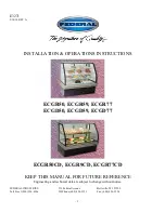
INSTALLATION & OPERATIONS INSTRUCTIONS 


ECGR50, ECGR59, ECGR77 
ECGD50, ECGD59, ECGD77 


ECGR50CD, ECGR9CD, ECGR77CD 


KEEP THIS MANUAL FOR FUTURE REFERENCE 

Engineering and technical data are subject to change without notice.


FEDERAL INDUSTRIES  


215 Federal Avenue 


Belleville, WI  53508 

Toll Free 1(800) 356-4206  


WI Phone (608) 424-3331  

Fax: (608) 424-3234 


Summary of Contents for ECGR50

Page 1: ...77 ECGD50 ECGD59 ECGD77 ECGR50CD ECGR9CD ECGR77CD KEEP THIS MANUAL FOR FUTURE REFERENCE Engineering and technical data are subject to change without notice FEDERAL INDUSTRIES 215 Federal Avenue Bellev...

Page 2: ...Product Into Case 10 SHELVING INSTALLATION REMOVAL 11 13 Shelves and shelf light quantity 13 SHELF INSTALLATION 13 Wire Shelves 13 Metal Shelves 13 MAINTENANCE 14 Shelf Light Bulb Replacement 14 Top...

Page 3: ...portions of this manual covering components contain technical instructions intended only for persons qualified to perform electrical work DANGER Improper or faulty hookup of electrical components in t...

Page 4: ...r death will occur if you ignore the message WARNING Severe injury or death can occur if you ignore the message CAUTION Minor injury or damage to your case can occur if you ignore the message NOTICE T...

Page 5: ...be located near open doors or main door entrances Also avoid locations where there are excessive air movement or air disturbances On refrigerated models the condenser air inlet and discharge is locat...

Page 6: ...ted Units DANGER Electric shock hazard Do not operate unit with panels removed There is a removable slotted panel at the rear of the case The panel allows access to the condensing unit the light balla...

Page 7: ...e sure that the drain line has not been dislodged during shipment and that the drain trap is located properly over the water reservoir of the condensate evaporator pan Cleaning For initial setup clean...

Page 8: ...ice must be grounded upon installation Optional Permanent Connected Models If this unit is designed for permanent connection to a power source See the electrical data plate located at the rear of the...

Page 9: ...ed in the on position and black in the off position Shelves Each display is furnished with shelves that are adjustable up and down and can be tilted in three angular positions See Shelving Installatio...

Page 10: ...loss Do not block the slots along the front or rear of the case display pan Covering these slots will block the refrigerated airflow and could cause product loss The display pan is removable for clean...

Page 11: ...m track by lifting doors upward until the bottom edge of door clears the lower track Swing the bottom of door outward and down out of top track 2 Insert a shelf bracket in the desired shelf standard s...

Page 12: ...n the appropriate shelf light cord plugs with the female light sockets and push together NOTE Do not roll plug during insertion 0 NOTCH 6 NOTCH 12 NOTCH 4 E1954 3 1 2 3 4 INSTALLATION REMOVAL 2 3 1 TO...

Page 13: ...ll prevent entire lighting system from operating SHELF INSTALLATION Wire Shelves 1 The Bakery models are provided with 22 wire shelves for the bottom and middle shelf and the 16 wire shelf is for the...

Page 14: ...units with rear swing doors completely open doors to allow access to interior of case 2 Remove all shelves shelf supports and Shelf lights from unit through rear door opening See Shelving Installatio...

Page 15: ...ilure to clean condenser coil will void condenser warranty 1 Disconnect power to the unit 2 Remove the back base panel located on the back bottom of unit by removing the panel retaining screws 3 Caref...

Page 16: ...all foreign materials from the door opening 2 Wipe complete interior of case using a damp cloth 3 Tilt the front glass forward as described in the illustrations below This will allow easier access to...

Page 17: ...ing any electrical components with water to prevent electrical damage to the case NOTICE Shut off light and power switches and remove all product from case Allow sufficient time for the unit to reach...

Page 18: ...soapy water Wipe off all soapy water with a damp cloth and allow todry NOTE Depending on the amount of usage and spillage of foreign material some fasteners may have to be removed and parts disassemb...

Page 19: ...cost and inconvenience of an unnecessary service call by first reviewing this checklist of frequently encountered situations that can cause unsatisfactory case performance CAUTION Before servicing cas...

Page 20: ...coil filter or condenser coil fins Check cold airflow Lack of adequate cold airflow could be a defective evaporator fan or blocked evaporator coil Check that paper or foreign material is not blocking...

Page 21: ...ng in the general area of the case Any case malfunction or housekeeping problem that creates a slip fall hazard around or under a case should be corrected immediately SALE DISPOSAL Owner Responsibilit...

Page 22: ...GD59 N A 0 9 N A N A N A N A 1 5 ECGD77 N A 1 3 N A N A N A N A 1 5 REFRIGERATED SELF CONTAINED ECGR50 24 0 7 0 4 1 2 8 8 58 8 10 5 ECGR59 26 0 9 0 4 1 2 8 8 58 8 11 6 ECGR77 30 1 3 0 8 1 2 10 1 68 14...

Page 23: ...DED M BLK G MAIN WIRING DIAGRAM DETAIL COLOR CODE B BLUE Y YELLOW W WHITE R RED BLK BLACK G GREEN W 60 HERTZ 1 PHASE 120 VOLTS GND L1 N BLK OPTIONAL POWER SWITCH 91 14145 8 16 99 FAN MOTOR BLK SEE LIG...

Page 24: ...BLK BLACK G GREEN G W 60HERTZ 1 PHASE 120 VOLTS GND L1 N BLK BLK RIB BLK RIB THERM W BLK G BLK BLK THERM G SEE LIGHT WIRING DIAGRAM DETAIL BLK EVAP FAN MOTOR BLK RIB BLK BALLAST SWITCH LIGHT SWITCH TO...

Page 25: ...O40T8 91 13924 04 16 01 BALLAST RECP PLUG G G SHELF LIGHT LAMP G TOP LIGHT LAMP COLOR CODE BLK BLACK B BLUE W WHITE Y YELLOW R RED G GREEN LIGHT WIRING DIAGRAM DETAIL BLK R T1 B T1 BLK B B S1 R B B R...

Page 26: ...AIL G BLK BALLAST BALLAST RECP PLUG G G SHELF LIGHT LAMP G LAMP BLK R T1 B T1 BLK B S3 B R R S3 SWITCH SEE MAIN WIRING DIAGRAM DETAIL B R A A W BLK BLK TO GROUND TO LIGHT SW BALLAST R BLK PLUG G G SHE...

Page 27: ...USED COLOR CODE BLK BLACK B BLUE W WHITE Y YELLOW R RED G GREEN R T1 G BLK BALLAST BALLAST RECP PLUG G G SHELF LIGHT LAMP G LAMP BLK B T1 BLK B S3 B R S3 SWITCH B R W BLK TO GROUND TO LIGHT SW BALLAS...

Page 28: ...8938 R 64 13122 ECGR59CD SA4846 4 50 18938 50 18938 L 50 18938 R 64 13122 ECGD59 SA4907 4 91 19102 91 19102 L 91 19102 R 64 14182 ECGR77 SA4846 5 50 18938 50 18938 L 50 18938 R 64 13122 ECGR77CD SA484...

Page 29: ...29...

Reviews: