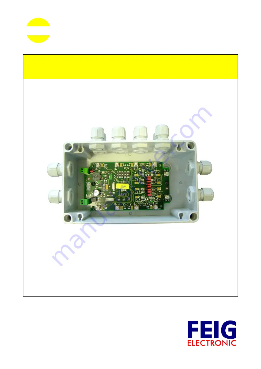
background image

MONTAGE

INSTALLATION

final
public (B)
2003-10-28
M30201-1de-ID-B.doc

OBID i-

scan

®

ID ISC.ANT.MUX

Antenna Multiplexer

(deutsch / english)

Summary of Contents for OBID i-scan ID ISC.ANT.MUX

Page 1: ...MONTAGE INSTALLATION final public B 2003 10 28 M30201 1de ID B doc OBID i scan ID ISC ANT MUX Antenna Multiplexer deutsch english...

Page 2: ...OBID i scan Montage ID ISC ANT MUX FEIG ELECTRONIC GmbH Seite 2 von 37 M30201 1de ID B doc D E U T S C H deutsche Version ab Seite 3 english version from page 21 E N G L I S H...

Page 3: ...bernimmt keine Gew hrleistung f r die Richtigkeit und Vollst ndigkeit der An gaben in diesem Dokument Insbesondere kann FEIG ELECTRONIC GmbH nicht f r Folgesch den auf Grund fehlerhafter oder unvolls...

Page 4: ...3 3 X1 Spannungsversorgung 8 3 4 X2 Eingang Optokoppler 9 3 5 IN1 2 Readeranschluss 10 3 6 OUT1 8 Antennenanschluss 10 4 Bedien und Anzeigeelemente 11 4 1 LEDs 11 4 2 DIP Schalter S1 12 4 2 1 Einstel...

Page 5: ...en die Gew hrleistungsbestimmungen des Herstellers in der zum Zeitpunkt des Kaufs g ltigen Fassung F r eine ungeeignete falsche manuelle oder automatische Ein stellung von Parametern f r ein Ger t bzw...

Page 6: ...ennen oder Gateantennen Basis und Erg nzungsantennen mit nur einem Reader betrieben werden Alle acht Ausg nge des Antennenmultiplexers k nnen ber Jumpereinstellungen jedem der beiden Eing nge zugeordn...

Page 7: ...uses Der Antennenmultiplexer ist f r die Montage auf W nden auch im Freien konzipiert Zur Wand befestigung befinden sich in den Ecken des Geh uses entsprechende Durchbr che siehe Bild 1 Bild 1 Masse u...

Page 8: ...nnungsversorgung Die Spannungsversorgung wird ber X1 angeschlossen Dabei ist die Polung gem Bild 3 anzu klemmen Der Antennenmultiplexer arbeitet bei einer Gleichspannung von 12V bis 24V Bild 3 Anschlu...

Page 9: ...gangsstrom sollte zwischen 10 mA und 20 mA liegen Je nach Ein gangsspannung sind Jumpereinstellungen gem Tab 1 vorzunehmen Tab 1 Jumpereinstellung f r Optokopplereingang ext Spannung Uext Rint JP19 JP...

Page 10: ...lichen Kabelverschraubungen zu f hren s Bild 6 Bild 6 Readeranschluss Hinweis F r das Erreichen optimaler Lesereichweiten sollte das Koaxialkabel entweder kleiner 50 cm oder 7 20 m lang sein 3 6 OUT1...

Page 11: ...er LEDs LED1 3 aufgelistet Tab 2 Funktion LED1 3 Kurzzeichen Farbe Beschreibung LED1 rot Diagnose 1 Kommunikations LED HF Communikation Control Mode Blinkt auf wenn der Multiplexer ein Signal vom Read...

Page 12: ...nstellung der Modi DIP Schalter S1 Adresse 1 2 3 4 5 6 7 8 reserviert ON Extern Trigger Mode 1 ON HF Communikation Control Mode 2 ON ON reserviert 4 2 2 Adresseinstellung im HF Communikation Control M...

Page 13: ...alter 3 und 4 aktiviert Ansonsten ist der Single Mode eingestellt s Tab 5 4 2 4 Einstellung Anzahl Ausg nge im Extern Trigger Mode ber die DIP Schalter 5 8 wird die Anzahl der verwendeten Ausg nge im...

Page 14: ...fgef hrt Tab 6 Beispiel Jumperstellung JP1 8 Jumperstellung Zuordnung Die Jumper JP1 8 stehen alle auf Position 2 3 Alle Ausg nge OUT1 8 sind damit dem Eingang IN1 zugeordnet Die Jumper JP1 4 stehen a...

Page 15: ...ird dem entsprechenden Ausgang OUT1 OUT8 eine DC Offset von 7V zugeschaltet Der maximale Gleichstrom der ber die Ausg nge flie en darf betr gt 100mA 4 5 Jumper JP19 und JP20 Mit den Jumpern JP19 und J...

Page 16: ...otwendig Die Protokolle sind im Handbuch H30701 d ID B aufgef hrt Durch die Kommunikation zwischen Reader und Multiplexer ist ein gezieltes Schalten bestimmter Ausg nge m glich Bild 9 zeigt ein einfac...

Page 17: ...eihenfol ge durchgeschaltet Die Jumperstellungen der Jumper JP19 und JP20 sowie die Pulsbreite des externen Triggersignal ist in Kap 3 4 X2 Eingang Optokoppler beschrieben Bild 10 zeigt ein einfaches...

Page 18: ...24 V DC Leistungsaufnahme max 4 W Betriebsfrequenz 13 56 MHz D mpfung pro Kanal max 0 5 dB max zul Schaltleistung 10 W RF Anschl sse 2 x Eingang 8 x Ausgang SMA Buchse 50 SMA Buchse 50 RF Schalter Sc...

Page 19: ...Seite 19 von 37 M30201 1de ID B doc D E U T S C H Umgebungsbedingungen Temperaturbereich Betrieb Lagerung 25 C bis 65 C 40 C bis 80 C EMV EN61000 6 3 EN61000 6 2 Vibration EN60068 2 6 10 Hz bis 150 H...

Page 20: ...OBID i scan Montage ID ISC ANT MUX FEIG ELECTRONIC GmbH Seite 20 von 37 M30201 1de ID B doc D E U T S C H...

Page 21: ...mation in this manual has been done to the best of our knowledge FEIG ELECTRONIC GmbH does not guarantee the correctness and completeness of the details given in this manual and may not be held liable...

Page 22: ...8 3 X1 Supply Voltage 26 8 4 X2 Input Opto Coupler 27 8 5 IN1 2 Reader Connection 28 8 6 OUT1 8 Antenna Connection 28 9 Operating and Display Elements 29 9 1 LEDs 29 9 2 DIP Switch S1 30 9 2 1 Settin...

Page 23: ...id at the time of purchase are valid for the device The manufacturer shall not be held legally responsible for inaccuracies errors or omissions in the manual or automatically set parameters for a devi...

Page 24: ...dual antennas base antennas or gate antennas base complementary antennas to be operated with just a single reader All eight outputs on the antenna multiplexer can be assigned to each of the two inputs...

Page 25: ...Installing the Enclosure The antenna multiplexer is designed for a wall mounted installation and is suitable for outdoor For wall attachment break outs are located in the corners of the enclosure see...

Page 26: ...pply Voltage The supply voltage is connected to X1 Configure the polarity as shown in Figure 3 The antenna multiplexer operates with a DC voltage of 12V to 24V Figure 3 Supply voltage connection X1 12...

Page 27: ...JP12 s Figure 4 The input current should be between 10mA and 20mA Set the jumpers according to Table 1 depending on the input voltage Table 1 Jumper settings for opto coupler input ext voltage Uext R...

Page 28: ...be routed through the sidewise cable fittings see Figure 6 Figure 6 Reader connection Note For optimum read distance the coax cable should be either less than 50cm or 7 20m in length 8 6 OUT1 8 Antenn...

Page 29: ...of LEDs LED1 3 Table 2 LED1 3 function Abbreviation Color Description LED1 red Diagnostic 1 Communication LED HF Communication Control Mode Flashes on when the multiplexer has received a signal from t...

Page 30: ...des DIP switch S1 Address 1 2 3 4 5 6 7 8 Reserved ON External Trigger Mode 4 ON HF Communication Control Mode 5 ON ON Reserved 9 2 2 Address Setting in HF Communication Control Mode The DIP switches...

Page 31: ...IP switches 3 and 4 Otherwise the single mode is acti vated see Table 5 9 2 4 Setting Number of Outputs in External Trigger Mode DIP switches 5 8 are used to set the number of outputs used in Single o...

Page 32: ...Table 6 shows two examples Table 6 Examples for jumper settings JP1 8 Jumper setting Assignment Jumpers JP1 8 are all at position 2 3 All outputs OUT1 8 are then assigned to input IN1 Jumpers JP1 4 a...

Page 33: ...With the Jumpers JP11 JP18 a DC Offset of 7V is switched on to the according output OUT1 OUT8 The maximum DC current for one output is 100mA 9 5 Jumpers JP19 and JP20 Jumpers JP19 and JP20 are used t...

Page 34: ...s necessary The protocols are described in the system manual for the H30701 e ID B The communication between the reader and multiplexer allows specific switching to a particular outputs Figure 9 shows...

Page 35: ...er in numerical order Jumper settings for jumpers JP19 and JP20 as well the pulse width of the external trigger signal is described in section 3 4 X2 Eingang Optokoppler Figure 10 shows a simple appli...

Page 36: ...C Power consumption max 4 W Operating frequency 13 56 MHz Attenuation per channel max 0 5dB max Permissible switching power 10 W RF connections 2 x input 8 x output SMA jack 50 SMA jack 50 RF switches...

Page 37: ...IC GmbH Page 37 of 37 M30201 1de ID B doc E N G L I S H Ambient Conditions Temperature range Operating Storage 25 C to 65 C 40 C to 80 C EMC EN61000 6 3 EN61000 6 2 Vibration EN60068 2 6 10 Hz to 150...

Reviews: