background image


F

EI

Y

T

ECH 


FY-41AP


A

UTOPILOT 

S

YSTEM


Airplane flight stabilization & Autopilot System 
Installation & Operation Guide


Guilin Feiyu Electronic Technology Co., Ltd 

Rm. B305, Innovation Building, Information Industry Park, Chaoyang Road, Qixing District, 

GuiLin, CN   

www.fyetech.com         


Email: fyetech@yahoo.com 

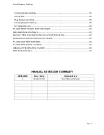
Rev: (0) April 16 2013 

Summary of Contents for FY-41AP Lite

Page 1: ...tabilization Autopilot System Installation Operation Guide Guilin Feiyu Electronic Technology Co Ltd Rm B305 Innovation Building Information Industry Park Chaoyang Road Qixing District GuiLin CN www fyetech com Email fyetech yahoo com Rev 0 April 16 2013 ...

Page 2: ...ed Current Sensor Power Manager 14 Gps Installation And Requirements 16 FY41AP Connection Summary 17 FY 41AP LED Instruction 18 Vibration Damping 19 Checking For Vibration Levels 20 In Flight Symptoms Of Too Much Vibration 20 Switch Channel Setting 21 SW2 Default Setting State 21 FY 41AP Installation Orientation 22 FY 41AP Installation Position 23 setting Correct Servo Direction 24 auto Balance Mo...

Page 3: ...T FLIGHT TEST CHECKLIST 39 Data Radio Gcs Software 40 Warning Pilot Input And Autonomous Flight Interaction 42 Fail Safe And Autonomous Return To Lauch 43 FY 41AP OSD INSTRUCTIONS 44 FY 41AP OSD Display Interface 45 Adjusting FY41AP Setting Via OSD 46 OSD Menu Interface 47 MANUAL REVISION SUMMARY REVISION Rev Date Update Note 0 16 April 2013 New Manual Release ...

Page 4: ...eed further technical support contact us at service feiyu tech com FY41AP overview a FY 41AP is an inertial attitude stabilizer for fixed wing multirotor aircraft b The FY41AP has an on screen display OSD hardware already integrated into the module making installation for FPV simple light and compact Critical flight information is displayed via your existing downlink system c Flight stabilization ...

Page 5: ...The display parameter outlay can be changed via RC control g Power Manager Module FY 41AP is supplied with an integrated Power Manager and Current Sensor module This module provides 5v power to the FY41AP RC Receiver and 12V FPV video camera and transmitter The current sensor sends battery voltage Amp draw and power consumption data to the FY41AP integrated OSD h Altitude control is achieved using...

Page 6: ...the altitude on activation By using GPS data the system automatically corrects flight course deviation maintains straight line flight Auto Circling Mode On activation the plane will maintain altitude and flight speed while initiating a counterclockwise circle The centre of the circle is the point of activation at a default radius of 80 meters can be changed via FY GCS Waypoint Navigation Flight Mo...

Page 7: ...1AP STANDARD CONFIGURATION 1 FY 41AP Control Module 2 Power Management Module 3 Airspeed Sensor 4 RC receiver connecting wires 5 USB cable 6 GPS module 7 4P Y cable 8 Velcro tape and damper pads Optional accessory 1 Data Radio 2 Remote Adaptor ...

Page 8: ...e installed in the following aircraft a Normal Traditional fixed wing planes b Delta winged plane with rudder c Delta winged plane without rudder d Plane without aileron e V tail plane with aileron f V tail plane without aileron g Any other configuration please consult us service feiyu tech com The FY 41AP has been tested to work with the following RC systems Robbe Futaba PPM PCM 1024 PCM G3 mode ...

Page 9: ...wer 5V Power 5V Power 5V Power 5V Power 5V Power 5V GND GND GND GND GND GND GND GND A The Yellow pins S1 S8 are signal output to aircraft servos S1 connect to Aileron servo 1 same signal as S5 S2 connect to Elevator servo S3 connect to ESC or engine throttle servo S4 connect to Rudder servo S5 connect to Aileron servo 2 same signal as S1 S6 not used for Airplanes LED Indicator View A View B ...

Page 10: ...t servos Important Note Power is supplied from the RC Receiver The power Pins in View A is not connected to the Power supply Pins of View B Do not short circuit the two sides C The bottom pins black colour are for GND ve D AS Airspeed Sensor connection port Please note signal ve and GND arrangement VIEW B Interface Diagram a GPS pins connection interface GND VCC GPS TXD GPS RXD GPS TXD Connect to ...

Page 11: ...UD Rudder RC Receiver port Ch 4 iv THR Throttle RC Receiver port CH 3 v ELE Elevator RC Receiver port CH 2 vi AIL Aileron RC Receiver port CH 1 vii VCC 5V power supplied from FY41AP to RC Receiver viii GND Connected to RC Receiver GND ve Connecting the FY41AP to the RC Receiver 1 FY 41AP requires a minimum of 6 channel RC receiver 2 4 Receiver channels are used for aileron Ch 1 elevator Ch 2 throt...

Page 12: ...via FY GCS a UART1 TXD TX port b UART1 RXD RX port c VCC 5V output port to power Data Radio or input power via PC USB supply during firmware upgrading d GND GND output port d UART2 module interface GND VCC UART2 TXD UART2 RXD This port is used to Connect to your PC via supplied USB cable to update the FY41AP OSD firmware a UART2 TXD TX port b UART2 RXD RX port c VCC 5V input via USB supply during ...

Page 13: ...Volt output supply to video transmitter and camera make sure your equipment is rated 12 volts d GND connect to video transmitter or camera ve e CS Current Sensor interface CS 12V VCC GND a CS Two pin interface for Current Sensor Data b 12V Provides 12V power to FPV Camera and video Transmitter c VCC Provide 5V power to FY41AP RC Receiver GPS Module Data Radio d GND Connect to Ground ve ...

Page 14: ...rvo 2 2 Connection for flying wing aircraft with or without Rudder S1 S2 S3 S4 Differential Servo 1 Differential Servo 2 ESC throttle servo Rudder servo 3 Connection for V tail aircraft with Aileron S1 S2 S3 S4 S5 Aileron servo 1 Differential servo 1 ESC throttle servo Differential servo 2 Aileron servo 2 4 Connection for V tail aircraft without Ailerons S1 S2 S3 S4 Differential Servo 1 Differenti...

Page 15: ...to the FY41AP and RC Receiver It also supplies regulated 12v to power the video transmitter and FPV camera c We DO NOT recommend using the internal BEC of your ESC to power the FY41AP as this is unregulated power The 5 female plug from the Power Manager sends 5V to power the FY41AP RC Receiver It also powers your 12v FPV Camera and Video transmitter The green yellow plugs send current sensor data ...

Page 16: ...hly recommend to use a 5v to 6v External BEC rated for 3A output plugged through VIEW A interface Remember to remove the red wire from your ESC plug if you use an External BEC e For Gas or Nitro powered planes you will require a 5 volt battery plugged into the RC Receiver The connecting wire will send 5v power to the FY41AP Warning remove the 5v wire from the Power Manager plug if you use battery ...

Page 17: ... fiber other shielding material which may block satellite signal reception c Install the GPS Module away from electromagnetic sources such as ESC s power wires servo wires video transmitters which can interfere with GPS signal d Wire interface Color Black Red White Function GND 5v GPS Data e Note that the FY41AP utilizes only the 5 volt version of the FY GPS Module Face Upwards ...

Page 18: ...Fyetech Electronics Technology Page 17 FY41AP CONNECTION SUMMARY ...

Page 19: ...lites Red blue flashes working modes While static and in any flight mode the LED flashes purple light this indicates the module needs a Gyro Reset Operating Mode LED Gyro Needs Reset or module senses movement GPS lock 4 Satellites Manual Mode Stabilized Mode 3D Mode Return To Launch Mode Fixed Altitude Heading Lock Flight Mode Preset Path Waypoint Navigation Mode Auto Circling Mode During Gyro res...

Page 20: ...s as shown below These damper pads will greatly reduce vibration reaching the module and provides adequate damping for most electric gas nitro powered planes c The algorithm in the FY 41AP compensates for normal levels of flight vibration However if the vibration exceeds the acceptable level stabilization will not work normally or may even stop working altogether d Install the FY 41AP away from th...

Page 21: ...tion Observe the state of the Red LED light If it stays OFF that means your vibration level is acceptable If instead the red LED lights up bright stays ON solid then vibration is too high You will need reduce the level of vibration on your aircraft Add additional damping change the FY41AP location or balance your engine propellers to reduce vibration IN FLIGHT SYMPTOMS OF TOO MUCH VIBRATION In the...

Page 22: ...witch to cancel Null position can the SW1 switch work c After programming your radio switches SW1 and SW2 please observe the LED Flashes to confirm correct mode setting SW1 DEFAULT SETTING STATE POSITION 1 2 3 servo signal output 900 1200US 1200 1800US 1800 2100US Function Manual Mode Stabilized Mode 3d Mode LED SW2 DEFAULT SETTING STATE Position 1 2 3 servo signal output 900 1200US 1200 1800US 18...

Page 23: ...ientations LOGO arrow to up down left or right Default installation orientation is logo up with arrow pointing forward direction of flight as shown below b If the default orientation is not possible you can change the orientation setting via the FY 41AP software Select orientation and confirm via Set button ...

Page 24: ...or flight deviation due to non horizontal installation can be corrected with using your RC Transmitter trims Plane roll remains level when in Auto Stabilization Mode FY 41A P Plane will roll to the right when in Stabilized Mode Plane will roll to the left when in Stabilized Mode FY 41A P FY 41A P Plane pitch remains level when in Auto Stabilization Mode FY 41A P Plane nose will pitch down when in ...

Page 25: ...io transmitter menu and reverse the channel as done normally AUTO BALANCE MODE ABM SERVO MOVEMENT CHECK SETTING a After the above is completed it is time to check the automatic stabilized servo movement b Activate the Stabilized Mode via your RC Transmitter 3 Way switch SW1 c Observe Automated AILERON movement Roll the plane as shown below and observe the servo movement RIGHT Roll the plane the ri...

Page 26: ...Manual Reversing the servo movement can also be done via your OSD downlink Refer Manual 22 Points d Observe Automated ELEVATOR movement Pitch the plane nose up down as shown below UPWARD Incline the plane nose the elevator should automatically move downwards DOWNWARD incline the nose elevator should automatically move upwards If the servo movement is incorrect reverse it via the setting software o...

Page 27: ...to the Left COUNTER CLOCKWISE rotation the rudder should move to the Right If the servo movement is incorrect reverse via the setting software or OSD f ESC THROTTLE CONTROL SURFACE MOVEMENT CHECK Check that the throttle function is normal in Autobalance Mode If the ECS Motor does not activate normally reverse the ESC signal output via setting software or OSD ...

Page 28: ...al position during reset However you must ensure there is no vibration or movement during the process INITIALIZATION RESET PROCESS a Power up the FY41AP keep stationary b Using your 3 Way switch move between Deactivated Mode and Auto Balance Mode 6 times over a period not longer than 3 seconds ABM Deactivated Mode ABM Deactivated Mode ABM Deactivated Mode ABM Deactivated Mode ABM Deactivated Mode ...

Page 29: ...manner b Before conducting this procedure please ensure you download the required software onto your computer 1 USB TTL device driver Download from FY website USB Driver 2 Software Setting Download from FY website SETTING SOFTWARE 3 Connect the FY41AP directly to your computer using the supplied USB cable make sure you follow the USB Plug cable colour as shown below ...

Page 30: ...ble find the COM port number 6 Open the setting software 7 Select the COM Port number Ensure the Baud rate is 19200 as shown below Press Connect or Auto Connect The Connect button will change to Disconnect upon successful connection Remove Red wire if using the FY41AP on board power Failure to do this may result in damage of your PC and FY41AP Check the COM Port number for Prolific USB to Serial C...

Page 31: ...or no stabilization to 100 for maximum stabilization Note that too low gain results is poor auto stabilization too high gain will cause oscillations of the aircraft Adjust your aircraft gain setting from the lowest gain and increase it until stabilization is optimum Never carry out your first test flight at maximum gain Aircraft oscillations can lead to crash Remember to press the Set button to sa...

Page 32: ...e plane position so that it is perfectly level ii Connect the FY41AP to your PC USB red wire removed iii Power up the FY41AP iv Connect to Setting Software v Activate Auto Balance Mode ABM check that all control surface are at neutral If not adjust via the servo links vi Press Record Attitude The FY41AP have now recorded your aircraft horizontal position Method 2 Accurate Method i In this method y...

Page 33: ...ls please see Remote Adaptor Data Radio manual 13 INSTALL SETTING FY 41AP supports four installation direction However the LOGO must be installed facing up FY 41AP has an arrow printed on the top of it Normally this arrow points towards the front direction of flight If you install the module in any other direction then default forward you need to set the module direction via the Install Setting op...

Page 34: ...lly iii Models selection table Aircraft Config Mix Setting Selection Remark Traditional aircraft layout with Aileron 1 Normal Navigation control using aileron 4 Normal RUD NAV Navigation control using rudder Flying wing aircraft 2 Elevons Navigation control using aileron Used for most kinds of flying wing planes 5 Elevons RUD NAV Used for flying wings with independent rudder for Navigation V Tail ...

Page 35: ...e function of each 3 Way switch position that controls the SW 2 channel ii NOTE SW 2 has priority over SW 1 Only when SW 2 is in the Null Mode can SW 1 work Therefore Null should be one of the options for SW 2 otherwise SW 1 will not work iii For the other two SW 2 switch positions you can select any of the following Navigation functions SW2 Mode Function Remark Null SW 2 Deactivated SW 2 set to N...

Page 36: ...ection for any of the listed channels AIL ELE THR RUD iii Press Set to confirm and save the direction reversal iv Check that the direction has been corrected after disconnecting the FY41AP from the PC 17 Circling Radius Setting i The FY41AP can fly over a set GPS point upon activation of Auto Circling Mode via switch SW 2 ii The default circling radius is 80 meters iii You may adjust this circling...

Page 37: ...tance setting it will automatically RTL v This feature of the FY41AP provides an additional aircraft Failsafe even when the RC Receiver has no failsafe feature vi The default Max Distance for the FY 41AP is 4000 meters You can reduce and increase this as you see fit 19 CRUISING SPEED SETTING i During Navigation Mode autonomous flight the FY 41AP will control its cruising speed via throttle control...

Page 38: ...Port see VIEW A 2 Install the sensor with at least 1 cm of the tube exposed to the outside air Ensure airflow is clear in front of the sensor If your airplane has propeller in front please install the sensor away from the propeller airflow This is to avoid wrong airspeed detection 1 cm Inside airplane Outside airplane ...

Page 39: ...nt pressure The difference between the two pressure data is calculated to provide an accurate aircraft airspeed 4 Airspeed sensor enables constant cruising speed control particularly in Navigation fully autonomous flight Cruising speed is set via the Setting Software 5 Upon plugging the Airspeed Sensor onto the FY41AP the OSD will display Airspeed If the Airspeed Sensor is removed the FY41AP will ...

Page 40: ...r completing the above basic check you can take off in either manual mode or ABM 7 If required adjust your transmitter trims until the plane fly level 8 Add plane roll pitch input and observe the rate of automatic balance action If recovery to level flight is too quick flight control feels sluggish then gain may be too high Land and adjust Gain according to the channel involved AIL ELE or RUDD 9 I...

Page 41: ... Technology Page 40 DATA RADIO GCS SOFTWARE i Refer to the FY Data Radio and FY GCS Manuals for more details ii Three data radio options are available FY606 2 4 Ghz 100mWatt FY602 433 mHz 500mWatt FY605 433 mHz 2000mWatt ...

Page 42: ...s including flight altitude speed flight path flight progress via the FY GCS software etc iv Various FY GCS software can be downloaded from the FY website www feiyudz cn The GCS version used depends on the processing capacity of your field computer v Remote Adapter allows you to fly the aircraft with only the FY41AP and Data Radio on board ...

Page 43: ...s normal The higher the Gain the stronger will be the leveling action of the FY41AP And the smaller the RC input you have on the aircraft To counter this reduce the Gain until you feel the plane s flying attitude is comfortable for your flying style d Alternately if the Gain setting is too low the aircraft self leveling will be weak and the greater the pilot manual control will be e In Navigation ...

Page 44: ...ruption of longer than 5 seconds the FY41AP will automatically activate RTL Therefore no Failsafe setting is required when flying in this configuration c MAX DISTANCE SETTING 1 The FY41AP has a Maximum Distance Setting function which you can adjust via the Setting Software 2 The Max Distance Setting will not allow the plane to fly beyond the distance you have set Upon reaching this distance the FY...

Page 45: ...D will immediately activate ii If there is no video input the OSD will only display the FY LOGO and wait for the incoming video input iii After the video stream is transmitted even when there is a break in camera video signal output the FY 41AP OSD will continue transmitting telemetry information via the video transmitter FLIGHT MODE ABBREVIATION Flight Mode Abbreviation Introduction RC Manual Fli...

Page 46: ...umed Unit mA h 6 Distance to Home Point Unit m 7 Power battery current Unit A 8 Flight mode 9 Current latitude longitude of the plane Format dddmm mmm 10 Relative altitude Unit m 11 Flight total mileage Unit km 12 Total flight time Format h m s 13 Current course of flight Unit deg 14 The angle of turning to the Home Point Unit deg 15 Attitude table 16 Relative position of Home Point Icon in the mi...

Page 47: ... 5 Once the Setting Via OSD display is called up on your video screen you can move the cursor using your Elevator stick 6 Carry out the required adjustment value via the Aileron stick e g increase or decrease the gain servo reversing 3 position swich arrangement etc 7 After completing the adjustment move the cursor using the Elevator stick to the Save position and use the Aileron stick to save the...

Page 48: ... 255 3 Aileron 4 Elevator 5 Throttle 6 Rudder 7 3 position switch mode 8 Install Setting 9 Flight Speed Unit m s 10 Flight radius Unit m 11 maximum distance Unit m 12 Link mode 13 Mix set 14 Initialize Gyro Airspeed meter 15 Record Attitude 16 Save 17 Exit END OF MANUAL Note This manual may be updated from time to time ...

Reviews: