background image

INSTRUCTIONS FOR USE INSTALLATION AND MAINTENANCE

OPTIMAX HE PLUS 25 OV

wall-mounted gas fired, 
pre-mix
condensing gas boiler

cod. 3540R580   -   02/2009  (Rev. 00)

5

Seasonal Efficiency 

(SEDBUK)

band A

G C N° 47-267-30

Summary of Contents for OPTIMAX HE PLUS 25 OV

Page 1: ...TRUCTIONS FOR USE INSTALLATION AND MAINTENANCE OPTIMAX HE PLUS 25 OV wall mounted gas fired pre mix condensing gas boiler cod 3540R580 02 2009 Rev 00 5 Seasonal Efficiency SED BU K band A G C N 47 267...

Page 2: ...ed engi neer The appliance may not be used for purposes other than those for which it was explicitly designed Any other use is considered improper and therefore dan gerous Incorrect installation and u...

Page 3: ...oiler water connections 11 2 4 Connection to the gas system 14 2 5 Electrical Connections 14 2 6 Flue system 17 2 7 Condensate outlet connection 23 3 SERVICE AND MAINTENANCE 25 3 1 Adjustments 25 3 2...

Page 4: ...boiler is totally room sealed from the installation room the air needed for combustion is drawn from outside The boiler also includes a modulating speed fan modulating gas valve safety valve temperat...

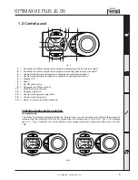
Page 5: ...ton 5 Display LCD 6 Reset 7 On Off push button 8 Domestic Hot Water symbol 11 Multi function indication 12 Degrees indication 13 Central Heating mode operation 14 Central Heating symbol 15 Burner on a...

Page 6: ...ies the Air purge function During the first 5 seconds the display shows the software version of the pcb Open the gas cock on the boiler and purge the air from the pipework upstream of the gas valve Wh...

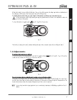
Page 7: ...function automatically whenever the external controls are calling for heat 1 4 Adjustments Heating temperature setting To set the system flow temperature use the CH push buttons Part 3 and 4 fig 1 It...

Page 8: ...a boiler shutdown In this case operation must be reset manually by pressing the reset Part 6 fig 1 for 1 second Other faults F indication cause temporary shutdowns that are automatically reset as soon...

Page 9: ...ation can cause damage or physical injury for which the manufacturer declines any re sponsibility This appliance must be installed strictly in accordance with these instructions and regulations The Ga...

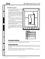
Page 10: ...l fixing must ensure a stable and effective support for the appliance using the bracket and fixings supplied If the unit is enclosed in a cupboard or mounted alongside there must be space for normal m...

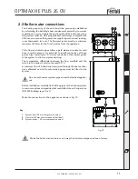
Page 11: ...ll type A drain cock device at the lowest points in the system to allow complete draining The temperature differential between the flow manifold and the return to the boiler should not exceed 20 C A m...

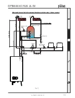
Page 12: ...matic type cylinders only indirect ones should be used The system must be fully pumped due to the complex design of the Aluminium Laminar heat exchang ers high efficiency design Attention is drawn to...

Page 13: ...ow Return Open Vent Motorised valve 22 mm DHW Isolating valve CH Pump Automatic By pass Motorised valve 22 mm CH Balancing valve 15 mm 22 mm Indirect cylinder Indirect coil missing 45 5 0 0 m m Open V...

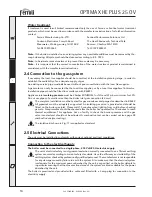
Page 14: ...ote If the boiler is installed on an existing system any unsuitable additives must be removed by tho rough cleansing All systems should be cleansed according to B S 7593 Note In hard water areas treat...

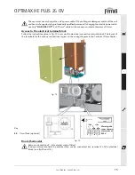
Page 15: ...ter of 8 mm Access to the electrical terminal block Follow the instructions given in fig 13 to access the electrical connection terminal block The layout of the terminals for the various connections i...

Page 16: ...ction Box N E L Terminal 5 SWITCH LINE 1 2 3 4 5 6 7 8 9 10 PROGRAMMER DHW ON CH ON NEUTRAL LIVE CH zone valve DHW zone valve Room Thermostat Cylinder Thermostat N E L 230 Vac BROWN BLUE GREY ORANGE L...

Page 17: ...he air inlet and flue outlet must be connected to one of the following flue systems With the aid of the tables and methods of calculation indi cated before commencing installation it is first necessar...

Page 18: ...f 3 mm per metre should be incorporated back to the boiler 3 Make a hole of diameter 10 20 mm greater than the nominal diameter of the concentric pipe used 4 If necessary cut the terminal length to si...

Page 19: ...e not supplied and correctly located into the sockets 3 If required 45 bends Part numbe r1KWMA64A maybeusedwitharesistance value of 0 5mtrs each the flue should be routedinsuchawaytoavoidanyunnecessar...

Page 20: ...de an equiva lent loss in linear metres depending on the position of installation of the component with air intake or flue extraction vertical or horizontal Thelossiscalled equivalentlength sinceitisc...

Page 21: ...Description Horozontial flue terminal Horozontial air terminal Vertical flue terminal 1 1 1 6 2 1 2 1 8 1 5 2 0 Equivalent losses in metres linear 5 2 Air Flue Vertical Horizontal Vertical Horizontal...

Page 22: ...wall Vertically from a terminal on the same wall From an opening in the car port e g door window into the dwelling Above ground roof or balcony level 300mm 300mm 300mm 200mm 75mm 200mm 150mm 100mm 300...

Page 23: ...ermissible with a vertical progression and with no constrictions Have the flue conveying the hot fumes adequately distanced or isolated from combustible mate rials Be connected to just one unit per fl...

Page 24: ...r as the condensate has a ph value of 4 slightly acidic Where it is not possible to terminate internally the condensate discharge pipe may be run outside see below drawing Any external run is subject...

Page 25: ...g as follows 1 Remove the casing 2 Open the sealed chamber 3 Release the fixing clip C and remove the gas pipeA from the fan venturi assembly 4 Replace the nozzle B inserted in the gas pipe with that...

Page 26: ...nd spin the pump Ensure the flue system is correctly fitted including terminal locations Ignition Open the gas valve upstream of the boiler Purge the air from the installation pipework to the applianc...

Page 27: ...erminal end piece and ducts must be free of obstructions and leaks The gas and water systems must be sound The burner and exchanger must be clean The electrodes must be free of scale and correctly pos...

Page 28: ...ention after performing all these operations to check and carry out all the phases of ignition and thermostat operation the gas valve and circulation pump After these checks make sure there are no gas...

Page 29: ...ctrode wiring Main board defective Check the PCB A03 High limit protection Flow sensor not active or correctly located Check the correct positioning and operation of the flow sensor No system circulat...

Page 30: ...or short circuited Check the wiring or change the sensor Sensor damaged or wiring broken Check the wiring or change the sensor F15 Fan problem Tachometer signal interrupted fan connection Check the wi...

Page 31: ...NICAL CHARACTERISTICS AND DATA 4 1 Dimensions and connections Key 1 System flow 22 mm compression union 3 Gas inlet 22 mm with isolation valve fitted 5 System return 22 mm compression union fig 26 80...

Page 32: ...mix fan assembly 19 Combustion compartment 22 Main burner 29 Flue Collar 44 Gas valve 81 Ignition electrode 201 191 29 22 81 82 161 154 196 19 278 5 16 186 44 7 193 82 Ionisation electrode 154 Condens...

Page 33: ...ydraulic diagram fig 28 Key 7 Gas inlet 10 CH flow 11 CH return 16 Premix fan assembly 44 Gas valve 154 Condensate outlet pipe 161 Heat exchanger 186 Return sensor 193 Siphon 278 Double sensor Safety...

Page 34: ...C directive Table 10 Gas Injector G20 Natural Gas Gas Injector G31 Propane Electrical protection rating IP Power voltage frequency V Hz X5D 230 50 98 3 97 3 105 4 107 2 109 1 Max working pressure in h...

Page 35: ...nal 81 Spark Electrode 82 Ionisation electrode 101 Main p c b 103 Relay 104 Fuse F3 15 amp 186 Return temperature sensor 191 Exhaust temperature sensor 202 Transformer 230V 24V 203 Supply lead 278 Dou...

Page 36: ...ED FOR THE DOMESTIC HOT WATER MODE MEASURE RECORD GAS RATE ft3 hr MAXIMUM BURNER OPERATING PRESSURE IF APPLICABLE mbar COLD WATER INLET TEMPERATURE C HOT WATER OUTLET TEMPERATURE C WATER FLOW RATE lts...

Page 37: ...TS SIGNATURE SERVICE 3 DATE ENGINEER NAME COMPANY NAME TEL No CORGI ID CARD SERIAL No COMMENTS SIGNATURE SERVICE 4 DATE ENGINEER NAME COMPANY NAME TEL No CORGI ID CARD SERIAL No COMMENTS SIGNATURE SER...

Page 38: ......

Page 39: ......

Page 40: ...down check this is not caused by lack of electricity supply gas supply or low water pressure before calling our Customer Service Helpline Lichfield Road Branston Industrial Estate Burton Upon Trent S...

Reviews: