background image


en

Operating 
instructions

8043786

1702a

[8043788]

Soft-start/quick exhaust valve

MS6-SV-...-D-10V24

Summary of Contents for MS6-SV-...-D-10V24

Page 1: ...en Operating instructions 8043786 1702a 8043788 Soft start quick exhaust valve MS6 SV D 10V24 ...

Page 2: ... serious injuries Caution Hazards that can cause minor injuries Other symbols Note Material damage or loss of function Recommendations tips references to other documentation Essential or useful accessories Information on environmentally sound usage Text designations Activities that may be carried out in any order 1 Activities that should be carried out in the order stated General lists è Result of...

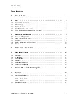
Page 3: ...ed personnel 8 3 2 Common cause failures CCF 8 3 3 PFHd value 9 3 4 Range of applications and certifications 10 3 5 Service 10 4 Control sections and connections 11 5 Application and function 12 5 1 Application 12 5 2 Designations 12 5 3 Switching logic 13 5 4 Function 13 5 5 Switching characteristics 14 5 6 Switch through pressure 15 6 Recommendation for activation and diagnostics 16 7 Installati...

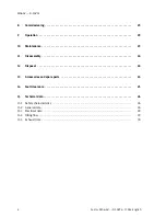
Page 4: ...ng 23 9 Operation 23 10 Maintenance 23 11 Disassembly 24 12 Disposal 24 13 Accessories and spare parts 24 14 Fault clearance 25 15 Technical data 26 15 1 Safety characteristics 26 15 2 General data 26 15 3 Electrical data 28 15 4 Filling flow 29 15 5 Exhaust time 30 ...

Page 5: ...e in this case both channels in a two channel system fail simultaneously If measures to control the CCFs are not observed the safety function of the soft start quick exhaust valve can be impaired Make sure that the described measures for managing the CCFs are observed è 3 2 Common cause failures CCF and 15 1 Safety characteristics Note Failure of the safety function Failure to observe the technica...

Page 6: ...d by switching off both coils The MS6 SV D is intended for installation in machines or automation technology systems and must be used exclusively as follows in an industrial environment within the limits defined by the technical data è 15 Technical data in its original condition without unauthorised modifications in perfect technical condition in accordance with the specifications of these operati...

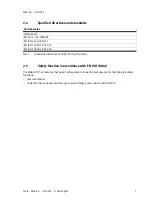
Page 7: ...1 EN ISO 13849 1 2015 12 EN ISO 13849 2 2012 10 Tab 1 Standards directives specified in the document 2 5 Safety function in accordance with EN ISO 13849 The MS6 SV D has features that permit achievement of a performance level e for the following safety functions pressure release protection from unexpected start up non switching in accordance with EN 1037 ...

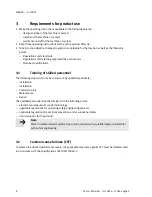
Page 8: ...ions 3 1 Training of skilled personnel The following steps must only be carried out by qualified specialists Installation Installation Commissioning Maintenance Repair The qualified personnel must be familiar with the following points electrical and pneumatic control technology applicable regulations for operating safety engineering systems applicable regulations for accident prevention and occupa...

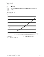
Page 9: ...MS6 SV D 10V24 1702a English 9 3 3 PFHd value The PFHd value depends on the version of the MS6 SV D and the annual actuation rate nop PFHd value MS6 SV D 1 2 1 PFHd 10 7 2 Actuation rate nop 104 a Fig 1 PFHd value MS6 SV D ...

Page 10: ...st values which the MS6 SV D must comply with and fulfil can be found in the section Technical data The product relevant EC directives and standards can be found in the declaration of conformity Certificates and declaration of conformity for the MS6 SV D è www festo com sp 3 5 Service Repairs may only be conducted with the parts listed in the spare parts catalogue è www festo com spareparts Openin...

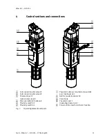
Page 11: ...ction pilot valve V2 3 Pneumatic port 2 output pressure p2 4 Pressure indicator optional 5 Proximity switch S2 6 Proximity switch S1 7 Pneumatic silencer mounted at pneumatic port 3 exhaust p3 8 Slot for proximity sensor S3 9 Valve body aJ Pneumatic port 1 operating pressure p1 aA Flow control screw for soft start function Fig 3 Operating elements and ports ...

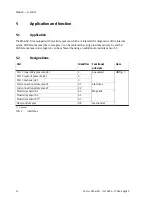
Page 12: ...rs S1 and S2 Performance level e in category 4 can be achieved by using an additional proximity sensor S3 5 2 Designations Port Identifier Functional principle Item Port 1 operating pressure p1 1 pneumatic è Fig 3 Port 2 output pressure p2 2 Port 3 exhaust p3 3 Coil connection pilot valve V1 V1 electrical Coil connection pilot valve V2 V2 Proximity switch S1 S1 Magnetic Proximity sensor S2 S2 Prox...

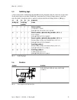
Page 13: ...on 1 closed passage from connection 2 to 3 opened 24 0 0 1 1 Normal position optional testing condition è Tab 6 Port 1 closed passage from port 2 to 3 opened 0 24 1 0 1 Normal position optional testing condition è Tab 6 Reduced flow via flow control valve from port 1 to 2 passage from port 2 to 3 opened 24 24 0 0 1 Switching position 1 Reduced flow via flow control valve from port 1 to 2 passage f...

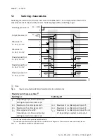
Page 14: ...n normal status Proximity switch response times1 Switching on Switching off t1 Depending on p1 flow control valve setting and system volume at p2 tS1 1 Maximum of 4 s after signal at V1 tS1 2 Maximum of 4 s after signal drop at V1 tS2 1 Maximum of 4 s after signal at V2 tS2 2 Maximum of 4 s after signal drop at V2 tS3 1 After signal at V1 and V2 Depending on p1 flow control valve setting and syste...

Page 15: ...used to generate a gradual pressure build up of output pressure p2 è Fig 10 The flow and thus the pressure rise can be adjus ted by turning the flow control screw When the output pressure p2 reaches about 50 of the operat ing pressure p1 the maximum flow rate is enabled 1 2 1 Ratio of p2 to p1 2 Filling time t Fig 5 Switch through pressure tolerance field ...

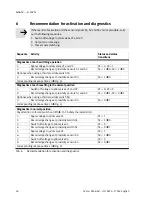
Page 16: ... at each resetting to the normal position 1 Switch off voltage to pilot valves V1 and V2 V1 0 V2 0 2 Record edge change at proximity sensors S1 and S2 S1 0 è 1 S2 0 è 1 Optional when using a third proximity switch S3 3 Record edge change at proximity sensor S3 S3 0 è 1 Corresponding response times è Fig 4 Diagnostics in normal position Pay attention to forced switch on off è 15 1 Safety characteri...

Page 17: ...ety function The safety function of pressure release might fail if the distance between the pneumatic silencer and base is not at least 15 mm Observe minimum distance of 15 mm below the pneumatic silencer è Fig 6 The open space ensures trouble free exhausting Information about mounting the module connector sub base and mounting bracket can be found in the operating instructions enclosed with the r...

Page 18: ...rientation è Fig 7 Fig 7 Flow direction 2 1 Assembly with MS series service units Note Failure of the safety function Incorrect installation in the service combination can result in failure of the pressure release safety function Only devices that do not impair pressure release also after a possible malfunction of the device may be placed downstream of the MS6 SV D ...

Page 19: ... MS6 END 1 cover cap if present from the side to be assembled slide upwards 2 Insert a seal 2 between the individual units module connector MS6 MV or mounting bracket MS6 WP WPB included in the scope of delivery 3 Place the module connectors 3 in the slots of the individual devices 4 Fasten the module connectors with two screws Fig 8 Assembly Max 1 2 Nm 1 2 3 ...

Page 20: ...eeding off a system through the MS6 SV D high sound pressure levels are generated We therefore recommend that you use a silencer The use of a commercially available silencer is possible However it must be able to bleed off as well as safety silencer UOS 1 è 15 2 General data Note Failure of the safety function When using a commercially available silencer the silencer may become clogged which can r...

Page 21: ...ance with EN IEC 60204 1 Note Long signal lines pick up more interference Make sure that the signal lines are always shorter than 20 m The signal lines must be run separate from lines that emit interference in accord ance with EN IEC 60204 1 Note The internal valves are sensed magnetically Make sure that there is no magnetic interference at the MS6 SV D Observe enclosed operating instructions for ...

Page 22: ...2 Proximity sensor S2 V2 Pilot valve 2 S3 Proximity sensor S3 Pot free Floating contact Emergency Stop Emergency stop input circuit Digital Output Digital output Feedback Loop Feedback circuit Digital Input Digital input Safety Device Safety switching device or safety PLC Standard PLC Programmable logic controller Tab 7 Designations in circuit examples ...

Page 23: ... operation and can be actuated The filling speed of the pneumatic system can be adjusted with the flow control valve è Fig 3 9 Operation Caution Danger of burns from hot pilot valves Do not touch the pilot valves during operation Note Perform a forced switch off at least once a month if the process related switching frequency is lower 10 Maintenance 1 Switch off the following energy sources to cle...

Page 24: ... recycled 13 Accessories and spare parts Proximity sensor Cable length m Port SMT 8M A PS 24V E 0 3 M12 0 3 M12 SMT 8M A PS 24V E 0 3 M8D 0 3 M8 SMT 8M A PS 24V E 5 0 OE 5 Open end Tab 8 Proximity sensor Solenoid valves Operating voltage DC V Port MSC 3 2 24VDC 24 Type C EN 175301 803 MSC 3 2 24VDC M12 24 M12 Tab 9 Solenoid valves Pneumatic silencer UOS 1 UOS 1 LF Tab 10 Pneumatic silencer Accesso...

Page 25: ...ened lines Provide low impedance paths to earth Pressure p1 collapses briefly at every switching op eration The cross section of the MS6 SV D pres sure supply is too small Tighten flow control screw a little Attach reservoir in front of inlet p1 Modify the compressed air supply e g increase cross section of the supply hose Tab 11 Fault clearance Perform the following steps if a malfunction occurs ...

Page 26: ...quency at least 1 month CE marking è Declaration of conformity In accordance with EU Machinery Directive 1 Depending on the average number of actuations per year nop Tab 12 Safety characteristics 15 2 General data MS6 SV D Port 1 2 G ISO 228 Port 3 G 1 ISO 228 Type of mounting In line installation with accessories Design Piston seat not free of overlap Actuation type electrical Pilot air supply In...

Page 27: ...in 9000 at p1 6 bar Min standard flow rate 2 3 in the event of the most critical error l min 6000 at p1 6 bar Min bleeding of the silencer UOS 1 l min 24 000 at p1 6 bar Residual pressure in normal condition bar 0 no residual pressure Max residual pressure for a worst case error1 bar 0 4 if p1 10 bar and flow control valve is fully open Switch through pressure Approx 50 of p1 è Fig 5 Filling flow ...

Page 28: ...N 60529 IP 65 fully mounted and connected Tab 14 Electrical data MS6 SV D Pilot valves Nominal DC operating voltage V 24 Permissible voltage fluctuations 10 Duty cycle 100 Nominal power per solenoid coil W 1 8 at 24 V DC Tab 15 Electrical data pilot valves Proximity sensor SMT 8M A PS 24V E Nominal operating voltage DC V 24 Permissible voltage fluctuations 10 Switching element function N O contact...

Page 29: ... 10V24 Festo MS6 SV D 10V24 1702a English 29 15 4 Filling flow Throttle flow rate qn as a function of the number of rotations n of the flow control screw p1 4 bar p1 6 bar p1 8 bar p1 10 bar Fig 10 Flow diagram ...

Page 30: ... status N Error status F Exhaust time s Operating pressure 3 5 bar Operating pressure 6 bar Operating pressure 10 bar to 1 0 bar to 0 5 bar to 1 0 bar to 0 5 bar to 1 0 bar to 0 5 bar 2 N 0 1 0 2 0 24 0 3 0 3 0 4 F 0 16 0 22 0 28 0 35 0 36 0 52 10 N 0 3 0 45 0 55 0 7 0 7 0 9 F 0 4 0 6 0 8 1 1 1 2 1 9 20 N 0 5 0 85 1 0 1 3 1 4 1 7 F 0 8 1 25 1 5 2 2 2 4 3 9 40 N 1 2 1 9 2 2 3 0 3 0 3 9 F 1 7 2 8 3 ...

Page 31: ...MS6 SV D 10V24 Festo MS6 SV D 10V24 1702a English 31 ...

Page 32: ...thorization is prohibited Offenders will be liable for damages All rights re served in the event that a patent utility model or design patent is registered Copyright Festo AG Co KG Postfach 73726 Esslingen Germany Phone 49 711 347 0 Fax 49 711 347 2144 E mail service_international festo com Internet www festo com ...

Reviews: