background image

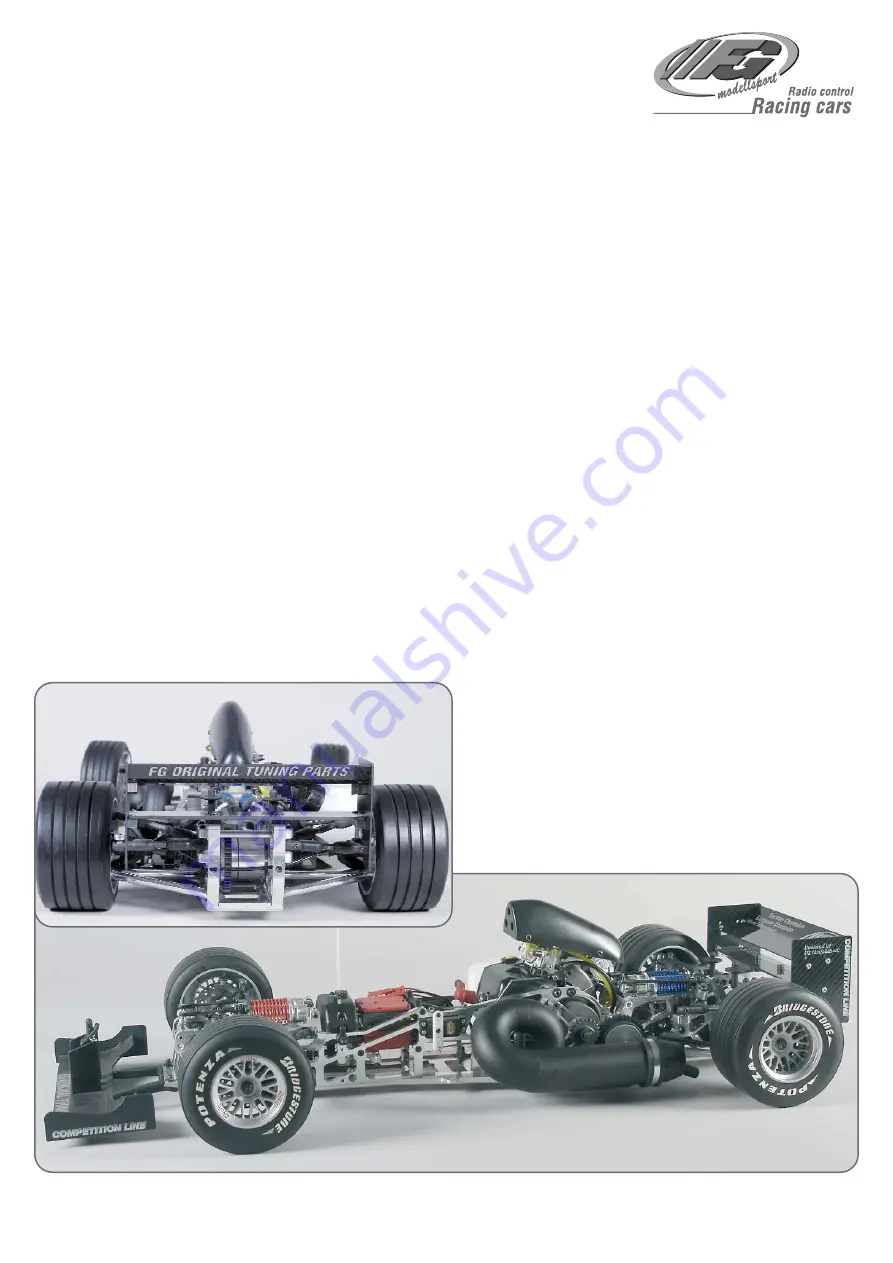
Mounting instruction for
F1 Competition 09 Chassis 
Item N°. 10007, 10008

A.10007-10008-200409

FG Modellsport GmbH
Spanningerstr. 2
73650 Winterbach-Germany
Phone: +49 7181 9677-0
Fax: +49 7181 9677-20
info@fg-modellsport.de
www.fg-modellsport.de

Please thoroughly keep this construction manual for spare parts orders!

Weight of the individual bags/ boxes:
Bag A

=

4 parts

Bag B

=

0,871 kg 

Bag C

=

0,649 kg

Bag D

=

0,617 kg

Bag E

=

0,308 kg

Bag F

=

0,136 kg 

Bag G

=

0,699 kg 

Bag H

=

0,729 kg

Bag I

=

0,091 kg

Bag J

=

0,125 kg 

Bag K

=

0,498 kg 

Bag L

=

0,442 kg 

Bag M

=

0,502 kg

Bag N

=

0,355 kg 

Bag O

=

0,587 kg, only for Item N°. 10007

Bag P

=

0,447 kg, only for Item N°. 10008

The RCS, accumulators and battery charger are not included in the de-
livery volume. 

We congratulate you on buying this FG Competition model. Please check
the contents of the construction set, respectively of the bags. The indi-
vidual bags had been thoroughly packed by us and their weight had been
checked. When purchasing the individual bags, please check their weight
and their closure by staples which must not have been removed or ope-
ned and closed several times. It is possible that the weight of an indivi-
dual bag deviates by 5 grams. In case of claims due to missing parts, you
always need to present the label indicating the weight at your speciali-
zed dealer. By checking the weight of the bag, you may exclude that lar-
ger parts or several parts are missing.

Summary of Contents for 10007

Page 1: ...ag P 0 447 kg only for Item N 10008 The RCS accumulators and battery charger are not included in the de livery volume We congratulate you on buying this FG Competition model Please check the contents of the construction set respectively of the bags The indi vidual bags had been thoroughly packed by us and their weight had been checked When purchasing the individual bags please check their weight a...

Page 2: ...tion When starting the engine avoid inhaling the exhausts The model must neither be started nor operated without air filter or without exhaust system Before every start perform a functional check of the safety relevant parts The throttle rods must always return automatically to the idle position Any cleaning maintenance and repair works must only be performed with the engine being switched off The...

Page 3: ... housing and carefully pull out the differential axle Push both bronze bushes 8600 8 from the inside to the outside into the bo rings of the differential housing position 1a Insert the differential gearwheels B into the housing and push in the differential bevel differential gear axle 6068 Grease the 8mm shaft of the ball diff axle 6069 2 plentifully and push it from outside into the differential ...

Page 4: ...11x8x1 Ball bearing 8x16x5 Bearing shaft Gearwheeel 38 teeth Distance bush 11x8x6 Guide bush Guide bush Differential mounted Alu Quer verstrebung Alloy cross bracing Alloy rear axle mount left Screw 4x18 Screw 4x18 Screw 4x18 Headless pin 4x10 Headless pin 4x10 Alloy wish bone fixing M4 Alloy wish bone fixing M4 Plastic wish bone fixing Ø4 Plastic wish bone fixing Ø4 Screw 4 2x19 S c r e w 4 2 x 1...

Page 5: ... left and right rear axle plates differ pay attention that the slant shows to the top when assembling Apply lubrication grease Lubricate ball driveshaft a little Protection bellow Ball diff axle Ball driving axle Distance disks Balls for dri ving shaft Position 5 Parts are in bag B 1 Press the cylinder pins into the square wheel 14mm as described in position 6 use high strength screw reten tion Pr...

Page 6: ...Position 8 Parts are in bag E Position 8a Parts are in bag E Position 8b Parts are in bag E Position 8e Parts are in bag E Position 8c Parts are in bag E Position 8d Parts are in bag E ...

Page 7: ...l 6mm Screw 4x20 Nut M4 Screw 3x12 Bearing bush Nut M4 Disk Ø 4 3 Assemble the M4x20 pan head screws into the damper fixing brace and secure them with M4 nuts Now mount the fixing brace to the alloy rear axle mounts by using M4x12 pan head screws and Ø4 3 disks Screw the M4x20 headless pins into the alloy baffle as pic tured and secure them by using Ø4 3 disks and M4 nuts Mount the alloy baffle to...

Page 8: ...g head screws M3x6 Mount the front lower alloy wishbone with the shorter side facing the front to the alloy chassis and the alloy front chassis by using M5x25 countersunk screws be vel disks and M5 stop nuts Mount bevel disks always with the thinner side facing the ball type nipple Fix the body mounts to the left and right front axle carriers using 4 2x19 countersunk screws Mount the right front a...

Page 9: ...xing rubber bushings and screws to the servo fi xing braces as described in position 14 Switch on your RCS and bring the steering servos in neu tral position The servo arms have to be shortened slightly corresponding the type For competition we recommend to use alloy servo arms Press the servo arms on the servos as pictured and fix them with the enclosed screws Preferably the servo arms should be ...

Page 10: ...rew 4x25 Headless pin 6x6 Front axle carrier left Ball bush Position 16a Parts are in bag I Brake servo Brake servo Cable clip Receiver battery Throttle brake servo Throttle Brake servo Screw 2 5x12 Push the securing disk in the 2nd groove of the driving axles then in sert it in the alloy uprights equipped with ball bearings according to the illustration position 17 Then mount the square wheel dri...

Page 11: ...e and se cure it with disks Ø4 3 and M4 nuts Mount the alloy baffle to the front axle carrier by using M4x12 pan head screws Mould the ball bearings 7x11x3 into the alloy reversing plate insert the bearing bushes through the alloy reversing plates which are equipped with ball bearings and mount it to the al loy baffle using M5x25 pan head screws and disks Ø5 3 Screw the ball and socket joints 6mm ...

Page 12: ... gear shaft which has the shorter flat sur faces Mount the alloy gear carrier to the surface of the gear shaft using M5x6 headless pins secure the plastic gearwheel with 42 teeth using a spacer washer and a M6x10 pan head screw Impress the gear shaft into the alloy bearing bush equipped with ball bearings Mount steel gearwheel 15 teeth using M5x5 headless pins and secure it in the gear shaft using...

Page 13: ...lutch please use the enclosed manual as an aid Mount the clutch blocks with clutch springs and spring guides into the clutch carrier Screw in M4x6 headless pins until they are fitted close ly to the spring guide however do not pretense the springs Fasten the cover disk using M3x5 pan head screws Mount the complete clutch to the engine using an M6x25 countersunk screw Disassemble the original air f...

Page 14: ...e alloy engine mount to the engine and the alloy rear axle carrier using M5x14 pan head screws M5x14 hexagon screw and disks Ø5 3 Hint At first only slightly tighten the engine screws and the screws for the engine mount Tighten all screws later when the complete unit is mounted in order to avoid warping Fix the tank mount complete to the tank as described in position 24a Mount the complete tank at...

Page 15: ...1 and moisten them with some 2 stroke oil then push the Steel Power Tuning pipe F1 carefully on the manifold wi thout damaging the o rings Press the silicone hose over the tension spring and fasten the manifold and Steel Power Tuning pipe F1 with the tension spring Mount the holding strap for the Steel Power Tuning pipe F1 to the CFRP chassis side part by using the M4x16 pan head screw disks Ø4 3 ...

Page 16: ...o arm of the throttle brake servos Push the collet pressure spring throttle pivot post and collet on the thrott le rods press the throttle pivot post on the M3x18 screw in the same time and mount it in the collets using M3 stop nuts and M3x3 headless pins Hint Do not tighten the M3 stop nut which is on the throttle pivot post the throttle pivot post needs to be moved easily Bend the throttle rods ...

Page 17: ...yamide front spoiler using 2 9x9 5 pan head screws Fix the adjustable body mount to the poly amide front spoiler using 4 2x16 countersunk screws Mount the support for the body mount with a body clip Mount the polyamide front spoiler to the al loy front chassis using M4x18 pan head screws disks Ø4 3 and M4 stop nuts Mount the CFRP lower wing to the alloy rear axle carrier with each 2 dampening rubb...

Page 18: ...e Brake disk Brake caliper Valve Protective cap Screw 3x30 Angle connection Stop nut M3 Snap ring for square wheel Mount the rear hydraulic brake as described in enclosed manual Bend the brake rods corresponding to the illus tration and the throttle pivot post Make sure it is of easy motion and it does not touch anything For neutral posi tion of the RCS the brake must be released and the gas must ...

Page 19: ...Parts are in bag O Position 31b Parts are in bag O Angle connection Brake pipe Screw 3x30 Protective cap Valve Brake caliper Brake disk Snap ring for square wheel Mount the front hydraulic brake as described in enclosed manual Bend the brake rods corresponding to the illus tration and the throttle pivot post Make sure it is of easy motion and it does not touch anything For neutral posi tion of the...

Page 20: ...escribed in enclosed ma nual For neutral position of the RCS the brake must be released and the gas must be in neutral gear Bend the servo rods correspon ding to the throttle pivot post Make sure it is of easy motion and it does not touch anything Snap ring for square wheel Position 32b Parts are in bag P Servo arm Throttle brake servo Collet Headless pin 3x3 Servo rods Balance Bowden cable Brake ...

Page 21: ...ollet Servo rods Brake guide rail Bowden cable Brake servo Screw 4x14 Headless pin 3x3 Position 33 Parts are in bag P Mount the front Tuning disk bra ke as described in enclosed ma nual For neutral position of the RCS the brake must be released and the gas must be in neutral gear Bend the servo rods correspon ding to the throttle pivot post Make sure it is of easy motion and it does not touch anyt...

Page 22: ......

Page 23: ... 1pce 7323 14 Starter ratchet G230 260RC CY 1pce 7323 15 Press spring G230 260RC CY 1pce 7323 16 Screw disks G230 260RC CY 3pcs 7326 8 Securing ring G230 260RC CY 1pce 7328 2 Spark plug cap 1pce 7328 8 Ignition coil G230 260RC CY 1 pce 7330 8 Scews f silencer M5x60 Zen CY 2pcs 7332 Silencer gasket Zenoah CY 2pcs 7334 8 Screw set engine 7335 Insulator gasket Zenoah CY 1pce 7336 Insulator 1 pce 7337...

Page 24: ... 7475 2 6738 4 6714 13 10027 10024 6714 13 6714 13 10035 1 7475 1 6922 25 10022 7 10023 7 10027 7 4466 4466 4429 2 4429 2 4429 2 4429 2 6922 20 10632 6922 25 6922 25 6738 5 7475 5 6917 6 6917 6 6925 25 6925 25 7475 3 10027 10021 7475 2 6932 14 6926 25 6734 5 4494 4 10353 3 6738 4 6925 25 10353 2 8514 8 6928 3 10183 6027 6 6027 6924 20 6026 6013 7155 1 7154 1 6912 16 8514 6 6929 4 6929 20 10480 1 1...

Page 25: ...80 2 10027 10024 6077 5 6926 25 6926 25 6734 5 4494 4 10353 3 10353 2 6027 6 6027 6924 16 6254 6925 20 8514 6 10480 3 6929 4 10480 1 6929 20 6734 4 6738 4 7475 2 6932 14 6734 5 8600 13 4405 1 10658 10655 10657 10184 6734 4 6738 4 6738 4 6920 14 6924 12 6069 2 7080 3 6080 1 4412 6079 1 6113 6738 5 6922 25 6922 30 10644 7475 5 10042 6925 35 6077 5 10660 1 6926 16 6922 20 10475 1 6077 8 6078 5 6107 1...

Page 26: ......

Page 27: ...Body mount adjustable 80mm 1pcs 07155 01 Support for body mount 6pcs 07200 01 Damper housing 04 short 1pce 07201 02 Upper shock absorber seal 04 2pcs 07201 03 Adjusting ring 04 2pcs 07201 04 Lower shock absorber seal 04 2pcs 07201 05 Guiding set 10pcs 07332 Silencer gasket Zenoah CY 2pcs 07384 FG Zenoah engine G260RC 07406 03 Tension spring f FG steel side power 1 5 1pce 07406 06 Mounting strap se...

Page 28: ......

Reviews: