background image

ORIGINAL INSTRUCTIONS DOC. 10063841 - Ver. AC - 08-2020

PROFESSIONAL SCRUBBING MACHINES

USE AND MAINTENANCE MANUAL

MMg

Summary of Contents for MMg base

Page 1: ...ORIGINAL INSTRUCTIONS DOC 10063841 Ver AC 08 2020 PROFESSIONAL SCRUBBING MACHINES USE AND MAINTENANCE MANUAL MMg ...

Page 2: ......

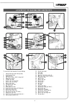
Page 3: ... lever 17 Squeegee control lever 18 Brush head extra pressure selection lever 19 Reverse gear selection lever 20 Service brake pedal 21 Drive pedal 22 Horn button 23 Recycle control button optional 24 Side brush control button optional 25 Emergency button 26 Operator seat 27 Recovery tank lid 28 Recovery tank 29 Solution tank 30 Right hatch 31 Left hatch 32 Squeegee support 33 Solution tank draina...

Page 4: ...OSAL 14 INSERTING THE BATTERIES INTO THE MACHINE 15 CONNECTING THE BATTERIES TO THE MACHINE S ELECTRICAL SYSTEM 15 RECHARGING THE BATTERIES 15 ASSEMBLING THE SQUEEGEE BODY 16 INSERTING WATER SYSTEM FILTER 17 FILLING THE SOLUTION TANK 17 DETERGENT SOLUTION 17 ASSEMBLING THE BRUSH HEAD BRUSHES SCRUBBING VERSION 17 FITTING THE SIDE BRUSH SCRUBBING VERSION 18 ASSEMBLING THE BRUSH HEAD BRUSHES SWEEPING...

Page 5: ...ARD RUBBER BLADES SWEEPING VERSION 32 CLEANING THE SIDE BRUSH SCRUBBING VERSION 32 CLEANING THE SIDE BRUSH SWEEPING VERSION 32 CLEANING THE WATER SYSTEM FILTER 32 CLEANING THE VACUUM HOSE 32 EXTRAORDINARY MAINTENANCE WORK 33 REPLACING THE SQUEEGEE BODY RUBBER BLADES 33 REPLACING THE BRUSH HEAD SPLASHGUARDS SCRUBBING VERSION 34 REPLACING THE BRUSH HEAD SPLASHGUARDS SWEEPING VERSION 34 REPLACING THE...

Page 6: ... instructions indicated for the safety of the operator and the device Danger symbol corrosive substances The operator should always wear protective gloves to avoid the risk of serious injury to the hands caused by corrosive substances Danger symbol battery acid leakage Indicates the danger of leaking acid or acid fumes from the batteries while they are being recharged Danger symbol moving carriage...

Page 7: ...ifficulties arise while using the machine If necessary remember that our assistance service organised in collaboration with our dealers is always available for advice or direct intervention IDENTIFICATION DATA For technical assistance or to request replacement parts always give the model the version and the serial number written on the relevant plate TECHNICAL DESCRIPTION The MMg is a floor scrubb...

Page 8: ...2885 9 KW 2 03 2 01 Theoretical maximum productivity m2 h 4530 3870 4260 Working width IEC 62885 9 mm 755 645 710 Working width with the side brush mm 850 940 Squeegee width mm 880 880 880 Nominal power of central brush head motor IEC 62885 9 W 500 450 680 Total width of brushes IEC 62885 9 mm 2x400 2x616 Total width of the abrasive pad IEC 62885 9 mm 1x710 Number of rotations of central brush hea...

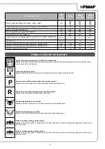
Page 9: ...he maximum temperature of the water that can be used to safely fill the solution tank Filter body position symbol Applied to the left hand side of the machine to indicate the position of the solution tank s filter P Extra pressure activation deactivation lever position symbol Applied to the central brush head s extra pressure activation deactivation lever R Reverse gear activation deactivation lev...

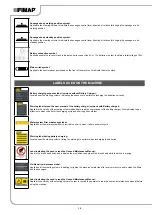
Page 10: ...s chaque usage Reinigungslösungstank immer nach jeder Benutzung säubern Water system filter maintenance label Applied near the water system filter to remind the user to clean it after each work cycle ATTENZIONE È fatto assoluto divieto di aspirare raccogliere con questo apparecchio polveri e o liquidi infiammabili e o esplosivi o particelle incandescenti ATTENTION It is absolutely forbidden to suc...

Page 11: ...e solution tank filter after every use Limpiar el filtro del tanque solución después de cada uso Nettoyer toujours le filtre du réservoir solution après chaque usage Reinigungslösungstank immer nach jeder Benutzung säubern Solution tank filter maintenance label Applied near the water system filter to remind the user to clean it after each work cycle PULIRE SEMPRE IL FILTRO DELL ARIA DOPO OGNI USO ...

Page 12: ...N OF MACHINE 12 1 2 5 1 2 5 7 2 8 9 10 6 8 7 11 9 R 3 4 12 3 4 10 11 12 13 13 14 15 14 15 16 17 18 16 18 17 20 19 19 20 21 23 22 21 24 22 23 25 27 25 26 24 25 26 28 29 27 28 29 30 30 31 31 32 33 34 32 33 34 35 6 ...

Page 13: ... following operations must be carried out by qualified personnel An incorrect connection of the connector may cause a malfunction of the device 8 Grip the handle 5 and lower the recovery tank to its working position 9 Sit on the driver s seat 10 Insert the key 2 into the main switch on the control panel Set the main machine switch to its I position by turning the key a quarter turn to the right Fi...

Page 14: ...rrect disconnection of the connector may cause a malfunction of the device 12 Grip the handle 5 and lower the recovery tank to its working position WARNING secure the device according to the directives in force in the country of use so that it cannot slide or tip over MACHINE SAFETY The procedure for securing the machine thus allowing the operations to be performed under conditions of complete saf...

Page 15: ... check that the characteristics of the battery that you are looking to use are appropriate for the type of work to be performed Check the battery charge and the condition of the contacts on the battery N B you are advised to only lift and move the batteries with lifting and transportation means suitable for the specific weight and size WARNING the lifting hooks must not damage the blocks connector...

Page 16: ...teries with the on board battery charger proceed as follows ATTENTION the following operations must be carried out by qualified personnel An incorrect connection of the connector may cause a malfunction of the device N B carefully read the use and maintenance instructions of the battery charger that is used for charging Remove the cap 14 from the battery charger socket Fig 14 Connect the connector...

Page 17: ...it Fig 22 4 Check to make sure that the water system s filter cap 23 located on the rear left hand side of the machine is closed if not close it Fig 21 The solution tank can be filled with water in two different ways Removing the cap measuring device 25 and filling the solution tank by means of a rubber hose or a bucket Fig 23 Using the filler hose 26 Fig 23 which supports the water hose on its ow...

Page 18: ...SSEMBLING THE BRUSH HEAD BRUSHES SWEEPING VERSION To assemble the brushes to bush head body which for reasons of packaging are supplied dismantled from the machine proceed as follows 1 Sit on the driver s seat 2 Insert the key 2 into the main switch on the control panel and move the main switch to position I by turning the key 2 a quarter turn to the right Fig 7 3 Turn the brush head control lever...

Page 19: ... is not the case empty it read DRAINING THE RECOVERY TANK on page 29 2 Check that the amount of detergent solution present in the solution tank is sufficient for the type of work to be performed If this is not the case top up the solution tank see the sections entitled FILLING THE SOLUTION TANK on page 17 and DETERGENT SOLUTION on page 17 3 Check the rubber squeegee blades are in good working cond...

Page 20: ... closed If it isn t close it Fig 6 17 Move to the front left side of the machine and check that the water tap is fully open move the water adjustment knob 6 in the direction shown by the arrow Fig 7 18 Move to the rear of the machine a check that the cap of the recovery tank drainage tube 7 is closed If it isn t close it Fig 8 19 Make sure the vacuum hose 8 is correctly connected to the sleeve 9 i...

Page 21: ...he control panel Fig 4 and the second screen that appears after the start up screen displays the percentage of charge of the batteries 8 N B When the minimum remaining charge is reached the graphic symbol 8 will start to blink and will turn off after a few seconds after which the symbol 9 will start to blink Under these conditions the machine must be brought to the battery charging area N B A few ...

Page 22: ...e liquid present in the vacuum hose is extracted N B when filling the solution tank it is good practice to empty the recovery tank using the special drainage hose DRYING To carry out DRYING WITHOUT SCRUBBING tasks proceed as follows 1 Carry out all the checks listed in the section PREPARING TO WORK on page 19 2 Sit on the driver s seat 3 Insert the key 1 into the main switch on the control panel a...

Page 23: ...s working position once the drive pedal is pressed the machine will begin to move in reverse and the brush head will remain in its working position but the solenoid valve will stop dispensing detergent solution to the brushes REGULATING THE DETERGENT SOLUTION To adjust the amount of detergent solution on the brush proceed as follows 1 Open the tap s output flow to maximum and shift the knob on the...

Page 24: ...er to help braking and also a mechanical brake If the machine is moving and the accelerator pedal 2 is released the machine brakes decelerating gently until it stops the encoder Only when the encoder has stopped is the electric brake engaged If the machine is moving and the brake pedal 10 Fig 12 is pressed the machine brakes according to the braking force of the mechanical system Only when the enc...

Page 25: ...ion Time out Actuator 3 AL_69 Function Amperometric Actuator 3 AL_70 Traction Overcurrent Actuator 3 AL_71 Traction Incorrect limit switches actuator 3 NUMBER TYPE DESCRIPTION AL_80 Traction Overtemperature AL_81 Traction Power board damaged AL_82 Traction Main fuse faulty AL_83 Traction Main contactor faulty AL_84 Traction Main contactor faulty CC AL_85 Traction Overcurrent traction output AL_86 ...

Page 26: ...y the recovery tank DRAINING THE RECOVERY TANK on page 29 Cleaning the vacuum system filters CLEANING THE RECOVERY TANK FILTERS on page 29 SQUEEGEE BODY Clean the vacuum chamber the squeegee rubber blades the vacuum nozzle CLEANING THE SQUEEGEE BODY on page 29 SOLUTION TANK Empty the solution tank EMPTYING THE SOLUTION TANK on page 30 Cleaning the detergent solution recycling system filter FLR ver...

Page 27: ... VERSION on page 18 REPLACING THE SIDE BRUSH SWEEPING VERSION on page 34 Check the condition and wear of the splashguard rubber blades in the brush head body REPLACING THE BRUSH HEAD SPLASHGUARDS SCRUBBING VERSION on page 34 REPLACING THE BRUSH HEAD SPLASHGUARDS SWEEPING VERSION on page 34 MONTHLY SQUEEGEE BODY Check the correct levelling of the rubber blades present in the squeegee body ADJUSTING...

Page 28: ...8 11 16 21 19 20 12 17 25 18 13 14 15 13 17 13 16 9 14 22 15 10 11 12 22 23 24 18 20 19 21 27 26 31 28 29 30 23 29 24 25 26 28 27 32 33 34 35 30 31 36 37 38 32 33 34 35 39 40 41 42 43 44 36 37 38 39 40 7 ...

Page 29: ...and use a spatula or a brush with soft bristles to eliminate any dirt that is particularly hard to remove 9 Remove the suction motor s duct filter from its support 6 Fig 7 10 Clean the suction motor duct filter under a jet of water N B Use a spatula to eliminate any dirt that is particularly difficult to remove 11 Dry the suction motor duct filter with a dry cloth and place it back on its support ...

Page 30: ...upport plate Fig 23 8 Unscrew the inspection cap 21 Fig 24 located beneath the seat s support plate 9 Rinse the inside of the solution tank with a jet of water 10 Once the work has been completed repeat the operations in reverse order to reassemble all the parts CLEANING THE RECYCLE FILTER FLR VERSION To clean the recycle filter proceed as follows 1 Close the detergent solution flow and shift the ...

Page 31: ...ver and have deformed bristles it is better to reassemble them in the same position the right hand one on the right and the left hand one on the left to prevent the different inclination of the bristles producing an overload on the brush motor as well as excessive vibrations 8 Once the work is complete refit the brushes see ASSEMBLING THE BRUSH HEAD BRUSHES SCRUBBING VERSION on page 17 CLEANING TH...

Page 32: ...ows 1 Stand on the right side of the machine 2 Remove the knob 38 fixing the side brush to the gear motor by rotating the right brush clockwise and the left brush anti clockwise Fig 42 3 Remove the washer 39 holding the side brush in place Fig 43 4 Extract the brush and clean it under a stream of running water to remove any impurities from its bristles N B Check the wear of the bristles and in cas...

Page 33: ...release the stopper 3 at the rear of the squeegee Fig 4 5 Remove the rear rubber blade 4 from the squeegee body and replace it with the new one Fig 5 6 Completely unscrew the knobs 5 in the squeegee body s pre assembly Fig 6 7 Remove the front rubber blade 6 from the body inside the squeegee and replace it with the new one Fig 7 8 Repeat the operations in reverse order to reassemble all the parts ...

Page 34: ...hine remove the splashguard rubber blade fixing screws 22 Fig 20 8 Remove the rubber blade compression plates 23 and the splashguard rubber blades 24 and replace them with new ones Fig 21 9 Repeat the operations in the reverse order and reassemble all the parts then move on to the right side squeegee N B remember to put the blade compression plate 23 between one splashguard rubber blade and the ot...

Page 35: ...tion entitled MACHINE SAFETY on page 14 WARNING It is recommended to wear the appropriate PPE Personal Protective Equipment suitable for the work to be carried out 6 Stand at the back of the machine Adjusting the height of the squeegee body Release the stopper lever 4 for the squeegee s height adjustment knob 5 Fig 4 Adjust the height of the rubber blade in relation to the floor by loosening or ti...

Page 36: ...onal Protective Equipment suitable for the work to be carried out 6 Go to the front left hand side of the machine 7 Open the machine s left lateral carter 11 Fig 14 8 Remove the side splashguard support by loosening the knobs 12 on it Fig 15 9 Adjust the height of the splashguard with respect to the floor tighten or loosen the handwheels 13 Fig 16 until the splashguard rubber blade is bent outward...

Page 37: ...same degree along its entire length at an angle of around 30 in relation to the floor Fig 11 N B Both the front and rear of the splashguard need to be at the same height off the floor 10 Once the adjustment is complete repeat the operations described above in reverse order to reassemble all the parts 11 Close the left hand lateral carter and repeat the operations just carried out on the right hand...

Page 38: ...2 180 655 PPL 0 3 BRUSH ØF 115mm ØE 180mm BLUE COLOUR 448012 2 180 655 PPL 0 6 BRUSH ØF 115mm ØE 180mm WHITE COLOUR 448013 2 180 655 PPL 0 9 BRUSH ØF 115mm ØE 180mm YELLOW COLOUR 448014 2 180 655 ABRASIVE BRUSH ØF 115mm ØE 180mm GREY COLOUR 449917 2 180 655 TAMPICO BRUSH ØF 115mm ØE 180mm CENTRAL BRUSH HEAD BRUSH TYPE SWEEPING VERSION CODE QTY Ø EXTERNAL TYPE OF BRISTLE NOTES 443853 2 330 PPL 1 BR...

Page 39: ...ectly inserted into the electrical outlet Check that the battery charger power supply cable plug is connected to the mains socket The characteristics of the mains power supply do not correspond to those required by the battery charger Check that the characteristics in the battery charger plate are the same as those of the mains supply The LEDs of the battery charger blink repeatedly Referring to t...

Page 40: ...ake sure the vacuum tube is free of obstructions see CLEANING THE VACUUM HOSE on page 32 Make sure the vacuum cap filter is free of obstructions see CLEANING THE RECOVERY TANK FILTERS on page 29 Make sure the suction motor filter is free of obstructions see CLEANING THE RECOVERY TANK FILTERS on page 29 The cap on the recovery tank drainage tube is not properly positioned Check that the cap on the ...

Page 41: ... 2014 30 EC Electromagnetic compatibility directive They also comply with the following standards EN 60335 1 2012 A11 2014 EN 60335 2 72 2012 EN 12100 2010 EN 60335 2 29 2004 A2 2010 EN 61000 6 2 2005 AC 2005 EN 61000 6 3 2007 A1 2011 AC 2012 EN 61000 3 2 2014 EN 61000 3 3 2013 EN 55014 1 2006 A1 2009 A2 2011 EN 55014 2 2015 EN 62233 2008 AC 2008 The person authorized to compile the technical file...

Page 42: ...ives 2006 42 EC Machinery Directive 2014 30 EC Electromagnetic compatibility directive They also comply with the following standards EN 60335 1 2012 A11 2014 EN 60335 2 72 2012 EN 12100 2010 EN 61000 6 2 2005 AC 2005 EN 61000 6 3 2007 A1 2011 AC 2012 EN 62233 2008 AC 2008 The person authorized to compile the technical file Mr Giancarlo Ruffo Via Invalidi del Lavoro 1 37059 Santa Maria di Zevio VR ...

Page 43: ......

Page 44: ...FIMAP S p A Via Invalidi del Lavoro 1 37059 S Maria di Zevio Verona Italy Tel 39 045 6060411 Fax 39 045 6060417 E mail fimap fimap com www fimap com ...

Reviews: