
Page 1
OWNER’S MANUAL
General Information
Thank you for purchasing this product. The purpose of this
manual is to assist you in operating and maintaining your lawn
& garden/ATV sprayer. Please read it carefully, as it furnishes
information which will help you achieve years of trouble-free
operation.
Warranty
Products are warranted for one year from date of purchase
against manufacturer or workmanship defects for home owner
usage and 90 days for commercial usage.
For technical assistance, visit our website @
www.fimcoindustries.com or call:
TOLL FREE @ 1-800-831-0027
Our Technical Support Representatives will be happy to help you.
To obtain prompt, efficient service, always remember to give the
following information…
Correct Part Description and/or part number
Model #/Serial # of your sprayer
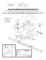
Part descriptions and numbers can be obtained from the illustrated
parts list section(s) of this manual.
www.fimcoindustries.com
1000 FIMCO Lane, P.O. Box 1700, North Sioux City, SD 57049
Toll Free Phone: 800-831-0027 : Toll Free Fax: 800-494-0440
[5004550
(06/15)]
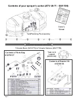
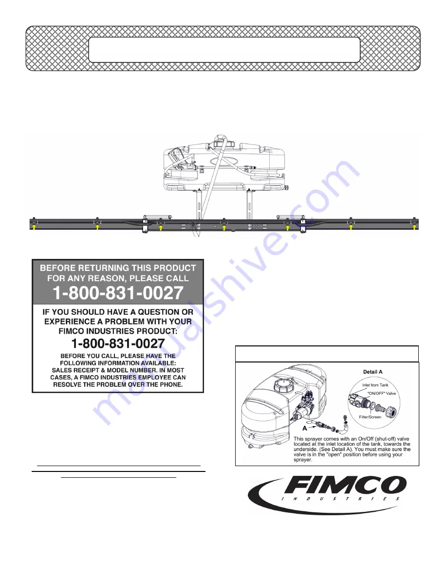
Model: ATV-25-71 (5301159)
(25 Gallon ‘Deluxe’ Lawn & Garden/ATV Sprayer
)
Caution: Always check the vehicle
load rating before using this sprayer.
The loaded weight of the sprayer and
boom assembly is about 280 lbs.
when the tank is full. Care must be
taken not to tip the vehicle over back-
wards, especially when starting or
accelerating.
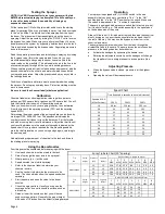
Technical Specifications
25 Gal. Corrosion-Resistant Polyethylene Tank
12 Volt Diaphragm Pump, 3.8 g.p.m.—45 psi
15 Ft. Handgun Hose (3/8” I.D.)
26 Ft. Vertical throw, 35 Ft. Horizontal Throw
Pressure Gauge
7-Nozzle Deluxe Boom Assembly
(140” Spray Coverage)
Corrosion-Resistant Nylon Nozzles
Bypass (Recirculation) Line
Assembly Instructions
Make sure the contents of the sprayer’s carton match the
items shown on page 2 of the manual.
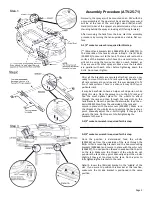
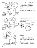
Follow the steps on pages 3, 4 & 5 to properly assemble
the sprayer.
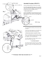
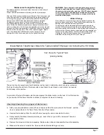
After assembly is complete and before testing your
sprayer, make sure you connect the electrical hook-up to
the end of your pump and clip the clips to a fully charged
battery. The red wire must be connected to the positive
(+) and the black wire should be connected to the nega-
tive (-).
The drain plug assembly should already be attached to
the tank
***IMPORTANT REMINDER***


