background image

Firepower

®


FP 125, FP 135, FP165


PORTABLE MIG/FLUX CORED WELDER

Révision :  

AC

    Issue Date:  

April 6, 2016           

Manual No.:  

0-5123

Operating 
Manual

www.firepoweronline.com

Summary of Contents for FP 95 FC

Page 1: ...Firepower FP 125 FP 135 FP165 PORTABLE MIG FLUX CORED WELDER R vision AC Issue Date April 6 2016 Manual No 0 5123 Operating Manual www firepoweronline com...

Page 2: ...re please take the time to read the entire manual especially the Safety Precautions They will help you to avoid potential hazards that may exist when working with this product YOU ARE IN GOOD COMPANY...

Page 3: ...e or in part without written permission of the publisher is prohibited The publisher does not assume and hereby disclaims any liability to any party for any loss or damage caused by any error or omiss...

Page 4: ...reof contained in this manual and accom panying labels and or inserts when installed operated maintained and repaired in accordance with the instructions provided This equipment must be checked period...

Page 5: ...3 2 3 07 Attaching the Gun and Cable Assembly to the Power Source 3 5 3 08 Polarity Changeover 3 6 3 09 Installing Wire Spool 3 7 3 10 Feedrolls 3 7 3 11 Install Wire into the Feedhead 3 7 3 12 Insta...

Page 6: ...eed Rolls 5 1 5 03 Basic Troubleshooting 5 1 5 04 Solving Problems Beyond the Welding Terminals 5 1 5 05 Welding Problems 5 2 APPENDIX 1 OPTIONS AND ACCESSORIES A 1 APPENDIX 2 REPLACEMENT PARTS A 2 AP...

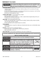
Page 7: ...d up no one is unprotected when the arc is struck 3 The workplace must be suitable for the purpose be free from drafts 4 Personal safety equipment Always wear recommended personal safety equipment suc...

Page 8: ...and wear protective clothing Protect bystanders with suitable screens or curtains FIRE HAZARD Sparks spatter can cause fire Make sure therefore that there are no inflammable mate rials nearby NOISE E...

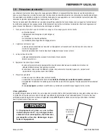
Page 9: ...lorsque l arc est amorc 3 Le lieu de travail doit tre am nag convenablement pour acqu rir le mat riel en toute s curit libre de courants d air 4 quipement de s curit personnelle Vous devez toujours ut...

Page 10: ...es tincelles projections peuvent causer un incendie Assurez vous qu il n y a pas de mat riel inflammable proximit de l appareil BRUIT un bruit excessif peut endommager la capacit auditive Prot gez vos...

Page 11: ...s 7 Operational Manual 8 0 5 lb Spool of Wire 9 Gas Hose The welding system is designed for use with the following processes 1 GMAW Gas metal arc welding MIG Requires the use of a shielding gas and re...

Page 12: ...A 120A 13 35A 155A 15 Wire Size Range Steel 023 030 035 0 6 0 8 0 9mm Stainless Steel 023 030 035 0 6 0 8 0 9mm 023 030 035 0 6 0 8 0 9mm Flux Core 030 035 0 8 0 9mm 030 035 0 8 0 9mm 030 035 0 8 0 9m...

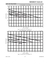
Page 13: ...35 0 0 10 20 30 40 50 60 70 80 90 100 110 120 130 140 OUTPUT CURRENT OUTPUT VOLTAGE Art A 09076_AB Figure 2 1 Volt Amp curves of the Firepower 125 FP 135 FIREPOWER Vin 115V 60Hz 0 5 10 15 20 25 30 35...

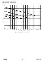
Page 14: ...ON 2 4 Manual 0 5123 FP 165 FIREPOWER Vin 230V 60Hz 0 5 10 15 20 25 30 35 0 10 20 30 40 50 60 70 80 90 100 110 120 130 140 150 160 170 180 190 OUTPUT CURRENT OUTPUT VOLTAGE Art A 09078_AB Figure 2 1 V...

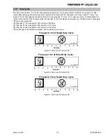
Page 15: ...5 must idle and be allowed to cool The thermal cutout will operate if the duty cycle is exceeded The Firepower FP 125 is designed for 19 duty cycle at 90 Amps The Firepower FP 135 is designed for 20 d...

Page 16: ...6 Manual 0 5123 2 08 MIG Gun Maintenance Remove dust and metallic particles from the gun conduit by forcing clean dry compressed air into the conduit once a week This will minimize wire feeding proble...

Page 17: ...rrent protection shall conform to the re quirements of the local electrical code All installation wiring and machine connection shall be done by a competent electrician SECTION 3 INSTALLATION The Nati...

Page 18: ...rst of gas This is called Cracking and is done to blow out any foreign matter that may be lodged in the fitting CAUTION KEEP FACE WELL AWAY FROM THE CYLINDER VALVE DURING CRACKING Never crack a fuel g...

Page 19: ...165 Manual 0 5123 3 3 INSTALLATION 1 Art A 07965 Cap 2 Shielding Gas Cracking 3 Shielding Gas Regulator and Flow Meter 4 Shielding Gas Shielding Gas 1 1 8 5 Gas Hose Figure 3 1 Gas Cylinder Installati...

Page 20: ...gulator must be opened to obtain a true flow rate reading on the outlet gauge Welding power source must be triggered Close the valves after the pressure has been set Art A 07280 Figure 3 2 Adjusting f...

Page 21: ...ollowed by the gun cable see Figure 3 3 NOTE Turn the cable end to align the gas hose nipple on the connector plug with the keyway located in the bottom of the front panel access hole 3 Loosen the scr...

Page 22: ...e door to the machine 2 Remove the polarity terminal knobs 3 Set up the polarity as per Table 3 1 above by remov ing the leads from the terminals and reversing them if necessary Refer to Figure 3 4 4...

Page 23: ...eedroll Example 3 11 Install Wire into the Feedhead WARNING ELECTRIC SHOCK CAN KILL Make certain the machine is unplugged from the power receptacle Do not plug machine in until told to do so in these...

Page 24: ...is being used Fig 3 10 5 Pass the wire into the Gun Liner of the Gun Cable End Fig 3 10 6 Close the Pressure Arm Fig 3 10 7 Close the Pressure Adjust Device Tighten it to a snug condition Fig 3 10 8...

Page 25: ...ltage Control Switch Power ON OFF Switch Figure 3 13 FP 135 165 Power ON 3 Set the wire feed speed to half way or 5 LOW 1 2 COARSE FINE HIGH v Art A 09061_AB Wire Feed Speed Voltage Control Switch Pow...

Page 26: ...FIREPOWER FP 125 135 165 INSTALLATION 3 10 Manual 0 5123 This Page Intentionally Blank...

Page 27: ...There are 4 positions available CAUTION The Voltage Control Switch MUST NOT BE SWITCHED during the welding process Some internal electrical components are at Mains voltage potential with this switch...

Page 28: ...ockwise rotation will tighten the brake Correct adjustment will result in the wire reel circumference continuing no further than 20mm after release of the Torch Trigger Switch The wire should be slack...

Page 29: ...o stabilize the arc Upon completion of the weld release the gun trigger switch raise the welding helmet and visually examine the weld NOTE To help you overcome any problems that might arise you will f...

Page 30: ...machine operated The process can be used to weld thin and fairly thick steels and some non ferrous metals in all positions Base Metal Arc Electrode Nozzle Shielding Gas Weld Metal Solidified Weld Met...

Page 31: ...e electrode wire is not energized until the gun trigger switch is depressed The wire may therefore be placed on the seam or joint prior to lowering the helmet Direction of Travel 90 Transverse Angle 5...

Page 32: ...hese variables cause changes in primary adjustable variables which in turn cause the desired change in the bead formation They are 1 Stickout distance between the end of the contact tube tip and the e...

Page 33: ...face protection fire compressed gas and preventative mainte nance See Safety Instructions and Warnings chapter included in this manual 4 11 Welding Procedure 1 Maintain the tip to work distance sticko...

Page 34: ...Decrease 3 Leading 2 Increase 5 Larger 4 Ar CO2 mix Larger Bead 1 Increase 2 Decrease 3 Increase Smaller Bead 2 Decrease 2 Increase 3 Decrease Higher Narrower Bead 1 Decrease 2 Trailing 3 Increase Fla...

Page 35: ...1 L1 L1 5 L1 3 5 L1 3 5 5 3 5 L1 L1 L1 5 6 6 7 5 5 4 8 5 6 4 5 3 7 4 4 4 7 4 3 5 3 5 L2 L2 H1 H1 H1 H1 H1 H1 8 6 5 8 5 7 5 6 5 H2 H2 H2 H2 H2 H2 6 7 5 6 5 H2 H2 H2 H1 L2 L2 L1 L1 L2 3 L2 L2 L1 L1 5 6...

Page 36: ...5 2 2 5 3 2 2 1 1 3 5 4 5 5 5 6 3 3 5 5 5 4 3 5 3 2 5 5 3 5 3 2 5 3 3 2 5 3 2 2 2 3 2 3 2 2 2 7 5 4 5 5 7 5 5 5 5 4 3 4 3 3 3 6 4 5 8 7 7 8 4 4 4 4 4 4 7 7 4 4 2 2 2 2 2 2 2 5 1 1 1 1 4 6 2 5 1 2 1 2...

Page 37: ...1 1 1 3 3 3 5 5 3 2 5 3 5 3 2 1 5 4 2 2 5 2 3 2 1 5 3 1 1 2 2 2 2 2 2 2 6 5 4 7 5 5 4 5 3 3 3 3 3 3 7 6 5 6 7 5 7 6 5 4 4 4 4 4 4 6 8 6 5 4 4 4 1 1 2 1 2 1 1 1 1 1 1 1 5 1 5 3 5 1 5 6 3 2 5 2 5 2 4 3...

Page 38: ...nd bead contour Good mechanical properties Greater than 3 32 See Note 1 Spray transfer 92 Argon 8 CO2 Flat HV Fillet Reduces undercutting Higher deposition rates and improved bead wetting Deep penetra...

Page 39: ...per minute 2 Gas leaks a Check for gas leaks between the regulator cylinder connection and in the gas hose to the Power Source 3 Internal gas hose in the Power Source a Ensure the hose from the solen...

Page 40: ...input C Increase the torch travel speed and or reduce welding current by reducing the voltage selection switch position or reducing the wire feed speed 2 Lack of penetration A Welding current too low...

Page 41: ...lding cable con nection B Check all welding cable connections C Low Primary Voltage C Contact supply authority 8 Arc does not have a crisp sound that short arc exhibits when the wirefeed speed and vol...

Page 42: ...ESAB FIREPOWER FP 125 135 165 SERVICE 5 4 Manual 0 5123 This Page Intentionally Blank...

Page 43: ...mm 1444 0026 Contact Tip 030 0 8mm 1444 0027 Contact Tip 035 0 9mm 1444 0489 Gas Diffuser 1444 0741 MIG Gun Complete Assembly 030 0 8mm Weld Wires Part No Description 1444 0210 1444 0211 1444 0215 144...

Page 44: ...GAS HOSE 1 5M CONN 9 16 CLAMPS 1444 0809 1444 0809 1444 0809 19 P C BOARD 1444 0483 1444 0483 1444 0465 20 MOTOR GEARBOX FP 135 1444 0803 W7004002 21 RECTIFIER 1444 0836 1444 0836 1444 0837 22 THERMOS...

Page 45: ...135 165 Manual 0 5123 A 3 APPENDIX 19 20 21 22 23 24 43 25 41 26 42 27 28 29 30 31 32 33 34 34b 35 36 37 38 39 A 09100_AB 1 2 3 40 5 7 8 6 9 1 2 1 3 4 5 7 8 6 9 13 Figure A 4 FP 125 135 165 Replaceme...

Page 46: ...FIREPOWER FP 125 135 165 APPENDIX A 4 Manual 0 5123 APPENDIX 3 FIREPOWER 125 SYSTEM SCHEMATIC Art A 09022...

Page 47: ...FIREPOWER FP 125 135 165 Manual 0 5123 A 5 APPENDIX APPENDIX 4 FIREPOWER 135 SYSTEM SCHEMATIC Art A 09023...

Page 48: ...FIREPOWER FP 125 135 165 APPENDIX A 6 Manual 0 5123 APPENDIX 5 FIREPOWER 165 SYSTEM SCHEMATIC Art A 09024...

Page 49: ...FIREPOWER FP 125 135 165 Manual 0 5123 A 7 APPENDIX This Page Intentiolnally Blank...

Page 50: ...FIREPOWER FP 125 135 165 APPENDIX A 8 Manual 0 5123 Revision History Date Rev Description 03 19 2009 AA Manual release 10 16 2015 AB Rebrand updates 04 06 2016 AC Updated Appx part numbers...

Page 51: ......

Page 52: ...2 22 ESAB international AB Gothenburg Tel 46 31 50 90 00 Fax 46 31 50 93 60 SWITZERLAND ESAB AG Dietikon Tel 41 1 741 25 25 Fax 41 1 740 30 55 UKRAINE ESAB Ukraine LLC Kiev Tel 38 044 501 23 24 Fax 38...

Reviews: