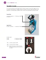
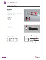
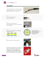
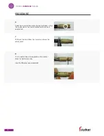
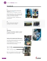
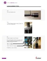
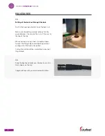
Fischer Connectors MINIMAX SERIES, Assembly Instructions Manual
The Fischer Connectors MINIMAX SERIES offers high-performance miniature connectors for demanding applications. Ensure proper assembly with the detailed Assembly Instructions Manual available for free download from 88.208.23.73:8080. Maximize the potential of your connectors with this essential manual.
Share
Download


Reviews:
No comments
Related manuals for MINIMAX SERIES

GSF Series
Brand: jbc Pages: 12

US232R-10
Brand: FTDI Pages: 30

102005
Brand: cable matters Pages: 2

SP-5004IZM-DA
Brand: GoMax Electronics Pages: 5

JN91H1
Brand: Senco Pages: 16

85-030
Brand: TACSWAN Pages: 6

26-458-01
Brand: NEC Pages: 12

PlasmaSync 61XM3
Brand: NEC Pages: 8

PlasmaSync 60XC10
Brand: NEC Pages: 2

PlasmaSync 61XM3
Brand: NEC Pages: 11

PlasmaSync 60XC10
Brand: NEC Pages: 10

PlasmaSync 60XR5A
Brand: NEC Pages: 20

SWV3113W
Brand: Philips Pages: 2

SWV3032S/10
Brand: Philips Pages: 1

SWV3021S/10
Brand: Philips Pages: 1

SWV3103W
Brand: Philips Pages: 2

SWV3101W
Brand: Philips Pages: 2

SWV3031W
Brand: Philips Pages: 2


