background image

BLACK INDUCTION COOKTOP

CI302DTB, CI603DTB, CI604DTB,

CI764DTB, CI905DTB models

INSTALLATION GUIDE

NZ AU GB IE SG HK

Summary of Contents for CI302DTB

Page 1: ...BLACK INDUCTION COOKTOP CI302DTB CI603DTB CI604DTB CI764DTB CI905DTB models INSTALLATION GUIDE NZ AU GB IE SG HK ...

Page 2: ...use or store flammable materials on or near this appliance z Packing elements eg plastic bags polystyrene foam staples packing straps etc and tools should not be left around during and after installation especially if they are within easy reach of children as these may cause serious injuries z Make sure you recycle the packaging material z Before disposing of any appliance make sure that it can no...

Page 3: ...er heated surface units cabinet storage space located above the surface units should be avoided If cabinet storage is to be provided the risk can be reduced by installing a rangehood that projects horizontally a minimum of 127mm beyond the bottom of the overhead cabinets During installation please ensure the following z Seal the exposed bare edges of the cutout with an oil based paint or moisture ...

Page 4: ...PARTS SUPPLIED TOOLS REQUIRED Wrench Clamping brackets 4 and screws 4 Hex key Crosshead screwdriver Foam tape 1 Router Silicone Cutter COMPONENTS REQUIRED 4 ...

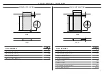
Page 5: ...8 E Width of chassis 260 F Depth of chassis 480 G Height of cooktop glass 6 H Depth of front overhang of cooktop glass 13 I Depth of rear overhang of cooktop glass 37 J Depth of side overhang of cooktop glass 20 Includes flange and tape Includes front trim Actual product dimension may vary by 2 mm FRONT FRONT A E B G J J FRONT PROFILE PROFILE D F H I FRONT PLAN ISOMETRIC B C 5 ...

Page 6: ... Height of cooktop glass 6 6 H Depth of front overhang of cooktop glass 13 13 I Depth of rear overhang of cooktop glass 37 37 J Depth of side overhang of cooktop glass 24 24 Illustrations show CI603DTB model cooktop Includes flange and tape Includes front trim PRODUCT DIMENSIONS 600MM MODEL Actual product dimension may vary by 2 mm B PROFILE iSOMETRIC FRONT PLAN FRONT PROFILE FRONT PROFILE FRONT P...

Page 7: ...sis 480 G Height of cooktop glass 6 H Depth of front overhang of cooktop glass 13 I Depth of rear overhang of cooktop glass 37 J Depth of side overhang of cooktop glass 19 Includes flange and tape Includes front trim PRODUCT DIMENSIONS 760MM MODEL Actual product dimension may vary by 2 mm FRONT PROFILE FRONT PROFILE FRONT PROFILE B A B E G J J D F H I C PROFILE ISOMETRIC FRONT PLAN 7 ...

Page 8: ...sis 484 G Height of cooktop glass 6 H Depth of front overhang of cooktop glass 13 I Depth of rear overhang of cooktop glass 33 J Depth of side overhang of cooktop glass 21 Includes flange and tape Includes front trim PRODUCT DIMENSIONS 900MM MODEL FRONT PROFILE FRONT PROFILE FRONT PROFILE PLAN B C FRONT A E B G J J PROFILE F H I D ISOMETRIC Actual product dimension may vary by 2 mm 8 ...

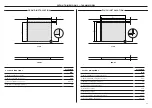
Page 9: ...nce 39 CUTOUT DIMENSIONS CI302DTB MM A Overall width of routered recess 305 B Overall depth of routered recess 535 C Offset overhang allowance 39 D Height of routered recess 5 E Width of cutout 265 F Depth of cutout 490 G Corner radius of routered recess max 2 H Corner radius of cutout max 10 PROUD INSTALLATION FLUSH INSTALLATION FRONT FRONT PLAN PLAN B f B A E A C H G D C D 9 ...

Page 10: ...TOUT DIMENSIONS CI603DTB CI604DTB MM MM A Overall width of routered recess 605 605 B Overall depth of routered recess 535 535 C Offset overhang allowance 39 39 D Height of routered recess 5 5 E Width of cutout 560 560 F Depth of cutout 490 490 G Corner radius of routered recess max 2 max 2 H Corner radius of cutout max 10 max 10 PROUD INSTALLATION FLUSH INSTALLATION FRONT FRONT PLAN PLAN B f B A E...

Page 11: ...ce 39 CUTOUT DIMENSIONS CI764DTB MM A Overall width of routered recess 765 B Overall depth of routered recess 535 C Offset overhang allowance 39 D Height of routered recess 5 E Width of cutout 725 F Depth of cutout 490 G Corner radius of routered recess max 2 H Corner radius of cutout max 10 PROUD INSTALLATION FLUSH INSTALLATION FRONT PLAN B A C D FRONT PLAN f B E A H G C D 11 ...

Page 12: ...ce 39 CUTOUT DIMENSIONS CI905DTB MM A Overall width of routered recess 905 B Overall depth of routered recess 535 C Offset overhang allowance 39 D Height of routered recess 5 E Width of cutout 870 F Depth of cutout 494 G Corner radius of routered recess max 2 H Corner radius of cutout max 10 PROUD INSTALLATION FLUSH INSTALLATION FRONT PLAN B A C D FRONT PLAN f B E A H G C D 12 ...

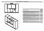
Page 13: ...30 D Maximum distance from right edge of cutout to center of junction box 762 E Minimum clearance below top of countertop to junction box 230 F Minimum clearance from countertop to overhead cabinet not directly above the cooktop 450 G Maximum depth of overhead cabinetry 330 H Minimum distance between overhead cabinets either side of the cooktop 315 I Minimum clearance from rear edge of cutout to n...

Page 14: ...0 30 D Maximum distance from right edge of cutout to center of junction box 762 762 E Minimum clearance below top of countertop to junction box 230 230 F Minimum clearance from countertop to overhead cabinet not directly above the cooktop 450 450 G Maximum depth of overhead cabinetry 330 330 H Minimum distance between overhead cabinets either side of the cooktop 315 315 I Minimum clearance from re...

Page 15: ...ace 30 D Maximum distance from right edge of cutout to center of junction box 762 E Minimum clearance below top of countertop to junction box 230 F Minimum clearance from countertop to overhead cabinet not directly above the cooktop 450 G Maximum depth of overhead cabinetry 330 H Minimum distance between overhead cabinets either side of the cooktop 315 I Minimum clearance from rear edge of cutout ...

Page 16: ...ximum distance from right edge of cutout to center of junction box 762 E Minimum clearance below top of countertop to junction box 230 F Minimum clearance from countertop to overhead cabinet not directly above wwthe cooktop 450 G Maximum depth of overhead cabinetry 330 H Minimum distance between overhead cabinets either side of the cooktop 315 I Minimum clearance from rear edge of cutout to neares...

Page 17: ...p at the front of the cooktop 4 B Minimum clearance from cooktop to drawer or other obstruction 65 C Minimum ventiliation gap at the rear of the cooktop 20 D Minimum diameter of cooling air hole 50 CLEARANCE DIMENSIONS MM A Minimum ventilation gap at the front of the cooktop 4 B Minimum ventilation gap at the rear of the cooktop 20 C Minimum diameter of cooling air hole 50 Some ovens require insta...

Page 18: ...mmer knife Take care not to damage the benchtop 4 Gently lower the cooktop into the cutout ensuring you have access below the countertop to fit and secure the brackets PROUD INSTALLATION 5 Locate the side brackets to the appropriate slots on the cooktop chassis The correct slot height is determined by the thickness of your countertop 6 Tighten all screws to secure the cooktop to the countertop Ens...

Page 19: ...countertop are protected Apply silicone in the gap between benchtop and cooktop Wipe off excess silicone 6 Adhesive tape 3 4 Tighten all screws to secure the cooktop to the countertop Ensure cooktop is level Locate the side brackets to the appropriate slots on the cooktop chassis The correct slot height is determined by the thickness of your countertop Gently lower the cooktop into the cutout ensu...

Page 20: ... 32A 7050W 220 240V 2N 380 415V 2N CI764DTB 32A 7400W 220 240V 2N 380 415V 2N CI905DTB 43A 9800W 220 240V 3N 380 415V 3N The CI302DTB is supplied with a cable This must be wired into a suitably rated plug permanent connection outlet or power isolator PE PE 1 2 3 4 5 N L N L1 L2 PE 1 2 3 4 5 N L1 L3 L2 PE 1 2 3 4 5 PE 1 2 3 4 5 N L N L1 L2 PE 1 2 3 4 5 N L PE 1 2 3 4 5 N L PE 1 2 3 4 5 N L PE PE 1 ...

Page 21: ...nd side to side All packaging materials have been removed There is constant flow of cool air from the cabinetry to the base of the cooktop Cooktop is securely clamped Basic operation has been demonstrated to the customer Cooking zones are functioning correctly Turn on all of them to a high setting and leave them on for at least one minute Touch controls and displays are functioning Receptacle with...

Page 22: ......

Page 23: ......

Page 24: ...nge at any time The product specifications in this guide apply to the specific products and models described at the date of issue Under our policy of continuous product improvement these specifications may change at any time For current details about model and specification availability in your country please go to our website or contact your local Fisher Paykel dealer ...

Reviews: