background image

Rocco

Model No. FBFL**RN3

LOG EFFECT BALANCED FLUE ROOM HEATER

Installation and Maintenance Instructions

Hand these instructions to the user

Model No. FBFL**RN3 is for use on Natural Gas (G20) at a supply pressure

of 20 mbar in G.B. / I.E.

** Denotes trim & colour variant

Summary of Contents for Rocco FBFL**RN3

Page 1: ...EFFECT BALANCED FLUE ROOM HEATER Installation and Maintenance Instructions Hand these instructions to the user Model No FBFL RN3 is for use on Natural Gas G20 at a supply pressure of 20 mbar in G B I E Denotes trim colour variant ...

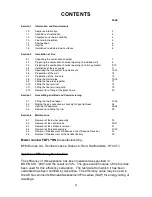
Page 2: ...mbling Fuel Bed and Commissioning 3 1 Fitting the fuel bed logset 21 25 3 2 Making the gas conection checking for gas tightness 26 3 3 Lighting the appliance 26 28 3 4 Removal re fitting the trim 29 Section 4 Maintenance 4 1 Removal of the burner assembly 30 4 2 Removal of the control valve 30 31 4 3 Removal of the ultrasonic reciever 31 4 4 Removal of the pilot assembly 31 32 4 5 Removal Replacem...

Page 3: ...Gas Rate 0 691 m3 hr High 0 325 m3 hr Low Cold Pressure G20 20 0 1 0 mbar 8 0 0 4 in w g Ignition Integral to gas valve Electrode Spark Gap 4 0mm Packed Weight Combustion Chamber 40 0 kg Pack 1 of 1 Packed Weight Flue Terminal Pack 16 0 kg Pack 2 of 2 Fig 1 Top View of Combustion Side View of Combustion Chamber Chamber 3 795 mm 728 mm 370 mm 364mm 150mm Diameter 138mm 75mm 550mm 465mm 138mm CRS 37...

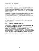
Page 4: ...Part 1 Installation of Gas Fires 2 B S 6891 Installation of Gas Pipework 3 B S 5440 Parts 1 2 Installation of Flues and Ventilation 4 I S 813 1996 Domestic Gas Installation issued by the National Standards Authority of Ireland 1 2 FIREPLACE SURROUND SUITABILITY The fire must only be installed on a hearth it must not be installed directly onto carpet or other combustible floor materials The fire is...

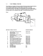
Page 5: ...ove an opening air brick 300mm 12in opening window C Horizontally to an opening air brick opening window etc D Below gutters soil pipes or drain pipes 300mm 12in E Below eaves 300mm 12in F Below balconies or car port roof 600mm 12in G From a vertical drain pipe or soil pipe 300mm 12in H From an internal or external corner 600mm 24in I Above ground roof or balcony level 300mm 12in J From a surface ...

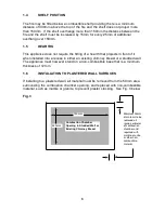
Page 6: ...s in either an existing chimney breast or a studded wall The appliance must however stand on a non combustible base that is a minimum thickness of 12mm 1 6 INSTALLATION TO PLASTERED WALL SURFACES If installing to a plastered wall all material must be removed from the 50mm area surrounding the combustion chamber opening and replaced with non combustible material such as marble or granite to prevent...

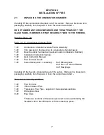
Page 7: ...1 off Boxed ceramic fuel bed set packed inside combustion chamber 1 off Installation Instruction Manual 1 off User Instruction Manual 1 off Flue Terminal Guard 1 off Loose Items pack containing 6 off M6 wingnuts 4 off No 12 x 40mm Screws 4 off Rawlplugs Carefully lift the flue kit components out of the carton Remove the loose item packaging carefully from the pack Check the contents as listed Pack...

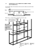
Page 8: ...0mm at sides Minimum 50mm at rear Combustion Chamber Dimension A Minimum Width 730mm Maximum Width 780mm Dim A Dim B Dimension B Minimum Height 540mm Dim C Dimension C Minimum Depth 380mm Fig 4 Fig 5 A minimum clearance of 100mm is required above the top of the flue pipe to combustible surfaces IMPORTANT ENSURE PLATFORM FOR SUPPORTING PRODUCT IS APPROXIMATELY 30MM BELOW THE BOTTOM OF THE OPENING T...

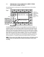
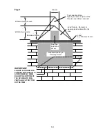
Page 9: ... is required see Fig 9 overpage If there is no existing openings within either triangle proceed with forming the opening However if opening or beams occur within either triangle then you should seek specialist advice from a structural engineer or consider relocating the proposed position of the firebox NOTE Please ensure that suitable cut outs in the sides and front face of the chimney breast are ...

Page 10: ...be assessed Load triangle No beam or opening permissible within this area Lintel e g 750mm x 75mm Proposed Opening in Chimney Breast Minimum 200mm Flue Pipe Installation Access 150mm IMPORTANT ENSURE PLATFORM FOR SUPPORTING PRODUCT IS APPROXIMATELY 30MM BELOW THE BOTTOM OF THE OPENING TO PRE VENT A GAP AT BOTTOM OF THE TRIM ...

Page 11: ...low Note Before breaking into the gas supply a gas tightness test should be carried out to establish that the existing pipework is sound 11 Combustion Chamber Gas Supply entering from L H S Combustion Chamber Gas Supply entering from Rear of Combustion Chamber Outer Cavity Wall or rear face of studwork Ensure if bringing gas supply through side or rear of a chimney breast that the pipe is sleeved ...

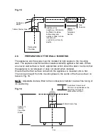
Page 12: ...90 degree elbow 3 off pipe clips This kit comprises the components required to fit the appliance into a studded wall or a chimney breast with a maximum depth of 880mm From Mounting Flange of Combustion Chamber to outer face of wall The main flue pipe section is a telescopic item which allows for a variation in depth of 160mm minimum to maximum length 250mm to 410mm See Fig 13 below Fig 13 12 Minim...

Page 13: ... the standard kit extra lengths of flue pipe are available from BFM Europe Ltd The lengths available and part no s are shown below B 83970 1000mm Flue Length Section B 83980 500mm Flue Length Section B 83990 250mm Flue Length Section B 84000 150mm Flue Length Section Always ensure that the solid section is fitted to the elbow when installing extra sections followed by the telescopic section as sup...

Page 14: ...ted onto is flat The minimum height from the mounting base to the centre of the flue is shown on below in Fig 16 NOTE Adjustable feet are fitted to the combustion chamber to allow fine tuning of it s positioning Fig 16 14 Additional Flue Length e g 1000mm to be fitted onto elbow before telescopic section is fitted to take into account variation in wall cavity depths 250mm to 410mm Telescopic Secti...

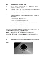
Page 15: ...roceed as follows Mark the position of the centre of the flue pipe as specified in figure 16 Mark the position of the hole around this point Chisel out the area as marked on the wall We then recommend that a cardboard cylinder is placed around the flue pipe and inserted in the chiselled out hole whilst making good NOTE If the appliance is to be installed into a building under construction it is re...

Page 16: ...anel on the combustion chamber See Fig 18 below Fig 18 c When the starter pipe is located tighten the 6 off wingnuts supplied in loose items pack to seal the starter pipe to the combustion chamber See Fig 19 below Fig 19 d Fit the 90 degree elbow in the required direction of the flue pipe L H R H or to the rear and secure to the starter pipe with the clamps as shown in section 2 9 16 ...

Page 17: ... located by pushing the sections together and clamping using the clamps provided As with all balanced flue appliances ensure that the flue sections are fitted together horizontally b The clamps are fitted together as shown below in Fig 20 21 Fig 20 Fig 21 17 ...

Page 18: ...formance of the product during adverse weather conditions See fig 22 below for correct positioning of the flue terminal Fig 22 18 Inner Cavity Wall Outer Cavity Wall Correct Position of Flue Terminal Flue terminal shown in correct position with inlet area flush with external wall Inner Cavity Wall Outer Cavity Wall Flue terminal shown in an incorrect position protruding beyond the external wall In...

Page 19: ...er the top of the flue terminal and attach to the wall using the No 12 x 40mm screws provided with the terminal guard See Fig 23 below Fig 23 NOTE In England Wales the building regulations require that a terminal guard should be fitted if the terminal could come into contact with people near the building or be subject to damage BFM Europe Ltd also recommend the fitting of a flue terminal guard whe...

Page 20: ...amp brackets as shown below in Fig 25 These are clamped together to form the seal between the glass frame assembly and the combustion chamber Fig 25 NOTE Always ensure that a consistent seal between the combustion chamber and the glass frame is achieved 20 Glass Frame Assembly locates over lip on top of combustion chamber lid and drops onto flange as shown To remove unclip base clips as shown in F...

Page 21: ... below in Fig 26 leaving the rear section as shown to allow the fitting of Log A Fig 26 b Place the largest Log A centrally onto the fuel bed support behind the burner flame strip Ensure that the fuel bed Log A is located centrally in the firebox and that the front edge is parallel with the rear face of the burner flame strip as shown below in Fig 27 Fig 27 21 A ...

Page 22: ...bed base log A as shown below in Fig 28 using the groove in Log A as a guide for placement Fig 28 d Fit Log C into position on left hand side of the fuel bed base log A as shown below in Fig 29 using the groove in Log A as a guide for placement Fig 29 22 B C ...

Page 23: ... base log A as shown below in Fig 30 using the groove in Log A as a guide for placement Fig 30 e Fit Log E into position at centre of the fuel bed base log A as shown below in Fig 31 using the groove in the centre of Log A as a guide for placement Fig 31 23 D E ...

Page 24: ...below in Fig 33 using the raised section in the base log as a guide for position Fig 33 IMPORTANT NOTE HAVING FITTED THE GRAVEL MATERIAL IN THE BASE OF THE COMBUSTION CHAMBER ENSURE THAT NONE OF IT IS ON THE BURNER FLAME STRIP OR IN THE PILOT ASSEMBLY IF MATERIAL IS OBSERVED VISUALLY ON THESE COMPONENTS REMOVE THE FUEL BED LOGSET REMOVE THE GRAVEL MATERIAL FROM THE BURNER AND OR PILOT AND RE FIT T...

Page 25: ...to accept such waste Protective clothing is not required when handling these articles but we recommend you follow the normal hygiene rules of not smoking eating or drinking in the work area and always wash your hands before eating or drinking This appliance does not contain any component manufactured from asbestos or asbestos related products Refit the glass frame as detailed in section 2 13 page ...

Page 26: ... purged from the supply pipe Bring the knob back to its start position and turn it several times to the pilot position The pilot should light Hold in the control knob for at least 10 seconds to allow the thermocouple to heat up Release the control knob If the pilot fails to light repeat the procedure as detailed above c Turn the left hand control anticlockwise to the large flame position and this ...

Page 27: ...0 0 mbar 1 0mbar 8 0 in w g 0 4 in w g with the main burner operating on high To turn off the main burner e Turn right hand control knob clockwise to the position marked or press the down button on the remote handset until the flame extinguishes at this point a clicking noise will be heard from the motor To turn off the pilot flame f Turn left hand control knob clockwise to the position marked and...

Page 28: ... TO RE LIGHT THE APPLIANCE Finally hand the Installation and Maintenance Instructions and the Users Instructions over to the customer and explain the operation of the fire NOTE THIS APPLIANCE IS DESIGNED TO WORK SAFELY AND EFFECTIVELY DURING ADVERSE WEATHER CONDITIONS HOWEVER DURING SUCH TIMES FLAME DISTURBANCE MAY BE NOTICED THIS IS NORMAL AND DOES NOT EFFECT OR IMPAIR THE SAFETY OF THE APPLIANCE...

Page 29: ...g lip on the rear face of the trim assembly over the top of the combustion chamber lid as shown below in Fig 36 37 Fig 36 Fig 37 b The aluminium trim is retained at the base of the firebox by the magnets supplied 29 Hook slots on trim into slots as shown below in Fig 37 Slots in lid of combustion chamber for mounting of the trim assembly ...

Page 30: ...sembly from the fire 4 1 1 Isolate the gas supply 4 1 2 Remove trim from the front of the fire as shown in section 3 4 4 1 3 Remove the glass frame assembly from the fire as shown in section 2 11 4 1 4 Remove the log set and loose gravel from the combustion chamber base taking care not to damage the logs 4 1 5 Remove the access panel from the front of the combustion chamber which is secured using ...

Page 31: ...g cradle attached to the L H leg of the combustion chamber 4 3 3 Re fit the new receiver in its cradle and re fit the control wires to the bottom R H side of the control valve 4 4 Removing the Pilot Assembly 4 4 1 Isolate the gas supply 4 4 2 Remove trim from the front of the fire as shown in section 3 4 4 4 3 Remove the glass frame assembly from the fire as shown in section 2 11 4 4 4 Remove the ...

Page 32: ... by removing the cover on the back of the handset Parts Shortlist Control Valve B 82290 Pilot Body 70 36250 Thermocouple 70 36270 Pilot Gasket 70 35220 Glass Panel B 81190 Glass Seal B 84180 Ignition Electrode 70 36290 Remote Control Receiver B 82350 Complete Log Set B 109780 Log A B 109700 Log D B 109730 Log B B 109710 Log E B 109740 Log C B 109720 Log F B 109750 Log G B 109760 Due to our policy ...

Reviews: