background image

User Manual

Air Handling Unit 

&

 Automatic Control

UNI 2

111537EN-11
2019-10

Summary of Contents for UNI 2

Page 1: ...User Manual Air Handling Unit Automatic Control UNI 2 111537EN 11 2019 10 ...

Page 2: ... 6 2 Idle mode 11 6 3 Menu navigation 11 6 4 Startup 11 6 5 Operating status 11 7 CI600 main menu 12 7 1 Fan speeds 12 7 2 Max timer 12 7 3 Settings 12 7 4 Temperature 12 7 5 Timer 13 7 6 Daily weekly timer 13 7 7 Time and date 14 7 8 Language 14 7 9 Filters 14 7 10 Alarm 14 7 11 Operating information 14 8 CI600 advanced user menu 15 8 1 PIN 15 8 2 Advanced user 15 8 3 Temperature regulation 15 8 ...

Page 3: ...uring service maintenance or in connection with an accident Important Safety Instructions This appliance can be used by children aged from 8 years and above and persons with reduced physical sensory or mental capabilities or lack of experience and knowledge if they have been given supervision or instruction concerning use of the appliance in a safe way and under stand the hazards involved Note tha...

Page 4: ...t is transferred to the supply air 1 4 Heating element EB1 for UNI 2 E If the energy recovered from the extract air is insufficient to maintain the set supply air temperature an electric heating element will help raise the temperature The heating element is protected against overheating by the thermostat F20 which cuts out at high temperature For extra safety the thermostat F10 cuts out at critica...

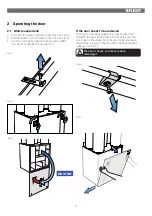
Page 5: ...t 180º see Fig 5 or unhooked see point 2 4 Fig 3 Fig 4 Fig 5 If the door needs to be removed The door can be removed when it is open between 40º and 105º If there is limited space in front of the unit the lock screw on the underside of the unit can be unscrewed temporarily see Fig 6 Then the door can be pushed out sideways see Fig 7 Fig 6 Fig 7 The door is heavy so take care when removing it MAX 1...

Page 6: ...e stops and a door strap are fitted see Fig 8 9 and 10 2 Undo the screw in the top see Fig 11 3 Pull the handles out and rotate to the side see Fig 4 4 The door can now be opened to a maximum of 105º se Fig 8 MAX 105 Fig 8 Fig 9 Fig 10 Fig 11 Fig 12 Fig 13 ...

Page 7: ...o a maximum of 105º see Fig 19 Check first that hinge stops are fitted see Fig 14 and 15 If not the door could fall off when opened Be careful Note that a door strap also needs to be fitted if the unit is mounted on the ceiling This protects the hinge stops against damage and prevents the door from opening more than 105 see Fig 16 MAX 105 Fig 14 Fig 15 Fig 16 Fig 17 Fig 18 Fig 19 ...

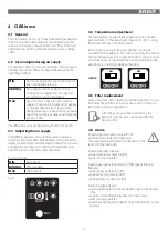
Page 8: ...on of ALARM 7 Indication of FILTER CHANGE No Description 8 Potentiometer for adjusting extract air at NORMAL speed 9 Potentiometer for adjusting supply air at NORMAL speed 10 Switch for additional heating ON OFF 11 Potentiometer for adjusting supply air temperature 12 Switch to reset alarm The numbers are used as references in subsequent descriptions Nos 8 9 and 10 are used to adjust the unit befo...

Page 9: ...N 50 fixed NORMAL 75 variable MAX 100 fixed 4 4 Temperature adjustment The temperature required in the supply air can be set with potentiometer 11 The adjustment range is 10 30 C Using the factory settings is recommended If necessary the ventilation unit s heating can also be switched ON OFF with switch 10 In this case only the rotating heat exchanger is used as a source of heat It is best to leav...

Page 10: ...n subsequent descriptions Fig 22 4 7 Reset After the filter has been replaced or the cause of the alarm repaired the alarm must be reset This is done by pressing switch 12 If the indicator goes out the action has been carried out correctly If the indicator remains on the fault has not been repaired correctly NB If thermostat F10 trips the unit will have to be opened up and physically reset before ...

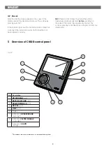
Page 11: ...lly How any problems affect the system is described in subsequent sections 6 CI600 in use 6 1 General The control unit consists of a colour display pressure switches and indicators LEDs See figure on left for more information The unit communicates with the ventilation unit via a low voltage cable 6 2 Idle mode The panel will go into idle mode if it is not used for a while Operating information is ...

Page 12: ... of the supply air is set TEMPERATURE 18 OK HEATING ELEMENT ON OFF C 7 CI600 main menu 7 1 Fan speeds The main menu contains various choices Most concern fan speeds The speed selected is indicated with large fan symbols and bold text MAIN MENU SETTINGS OK MIN NORMAL MAX MAX TIMER To change the speed move the cursor with buttons 1 and 3 MAIN MENU SETTINGS MIN NORMAL MAX MAX TIMER OK Then confirm yo...

Page 13: ... Timer 7 6 Daily weekly timer Programming the timer begins with selecting the day DAY WEEK SETTINGS MONDAY TUESDAY WEDNESDAY THURSDAY FRIDAY SATURDAY SUNDAY OK A new menu screen appears under each day TUESDAY 1 08 00 16 00 MIN 16 2 16 00 18 00 NORMAL 18 3 18 00 19 00 MAX 16 4 19 00 24 00 NORMAL 18 Each day can be programmed with four different time intervals Adjust the start and stop times for eac...

Page 14: ...larm has been reset the countdown to the next filter change begins 7 10 Alarm If a problem occurs in the operation of the ventilation unit an alarm will be tripped The red indicator 9 lights up and an information text appears in the display Follow the instructions in the text It is possible to go directly to this dialog from the message or via the menu tree NB If thermostat F10 trips the unit will...

Page 15: ...EGULATION REGULATION TYPE COOLING NEUTRAL ZONE EXT TEMP CONTROL OK Regulation type If supply air regulation is selected no further settings can be set here If extract air regulation is selected the max and min supply air temperatures can also be specified REGULATION TYPE REGULATION MAX SUPPLY AIR TEMP MIN SUPPLY AIR TEMP EXTR OK 35 15 Cooling NB Flexit does not supply or project cooling machines I...

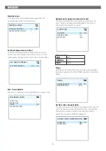
Page 16: ... supply air and extract air This dialog is identical for the supply air and extract air fans The fans are adjusted individually to the desired capacity for the respective speed SUPPLY AIR MIN SPEED NORMAL SPEED MAX SPEED OK 50 75 100 Factory settings MIN 50 NORMAL 75 MAX 100 Timer Settings are entered in this menu for the speed and time that are to apply to the MAX TIMER function in the main menu ...

Page 17: ... 0 If the pressure guard is activated an external sensor must be connected to the control card The sensor replaces the integrated filter time control FILTER GUARD ACTIVATION OK OFF Fire Smoke This function requires an external sensor to be connected to the control card FIRE SMOKE MODE OK 1 Mode Supply air fan Extract air fan 1 STOP STOP 2 MAX MAX 3 STOP MAX 4 MAX STOP Communication Proceed to the ...

Page 18: ...4 60 min 1 TIM 50 De icing Activates deactivates the function Start temperature The start temperature for the defrosting function is set here The temperature in question is the outdoor temperature Period time Period time for de icing operation Frequency Decides how many times the period shall be repeated per hour Rotor speed When the start temperature has been reached the speed of the drive motor ...

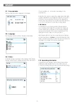
Page 19: ... TYPE CONFIGURATION TEST COMMUNICATION HOME AWAY OUTDOOR AIR EXTRACT AIR COOLING COOLING RECOVERY FACTORY SETTINGS SPECIAL FUNCTIONS IDLE MODE FILTER GUARD EXT TEMPERATURE CONT DAY WEEK SETTINGS TIME AND DATE SUNDAY OPERATING TIME ALARM START STOP SEQUENCE RETURN WATER TIMER NEUTRAL ZONE SERVICE LANGUAGE FILTER RESET FILTER ALARM ALARM FILTER CHANGE INTERVAL ADVANCED USER PIN PARAMETERS DE ICING A...

Page 20: ... To take out the filters 1 Pull the filter drawer out as far as it will go see Fig 24 The drawer does not have to be removed completely 2 The filter is now loose and can be removed 3 Put a new filter in and push the drawer properly into place When changing the filter check that the whole unit is working normally Use the following checklist Check that the rotor is rotating Turn the rotor in the dire...

Page 21: ...k on the spring under the fan housing and pull the housing sideways see Fig 27 1 and 27 2 Then take the fan housing out of the unit Take care not to damage the seal when you pull the fan housing out To take out the bottom fan 1 Pull out the electric quick release contact for the fan see Fig 26 2 Undo the safety screw and pull the fan housing out of the unit see Fig 27 1 and 27 2 Take care not to d...

Page 22: ...22 Fig 27 2 1 1 2 Fan Seal Fan Seal ...

Page 23: ...23 1 3 2 4 Fig 28 ...

Page 24: ...rew for the electric cover see Fig 28 1 and take the cover off 2 Disconnect the rotor s quick release contact from the circuit board by pressing the release down and pulling the contact see Fig 28 2 3 Undo the safety screw for the rotor module see Fig 28 3 4 Pull the rotor module straight out 5 Remove the screw in the centre of the aluminium profile and pull the profile out see Fig 29 6 Pull the b...

Page 25: ... clean the rotor If for various reasons it should still be necessary dust can be removed with a soft brush Further cleaning is possible by removing the rotor spraying it with a grease solvent and then blowing it clean from the opposite side Distance approximately 60 mm and max pressure 8 bar Ensure that the motor is not exposed to water during cleaning Ensure that all seals around the rotor are in...

Page 26: ... strips are intact and sit tightly against the rotor If they are worn they can be moved to the next groove in the profile so that they are closer to the rotor 3 years Inside unit A combination of a very low outside temperature and damp extract air can lead to the formation of ice Normally this will not be a problem when normal operating conditions return the ice crystals will be converted to steam ...

Page 27: ...on unit The right to give notice of lack of conformity applies to this product in accordance with the existing terms of sale provided that the product is correctly used and maintained Filters are consumables The symbol on the product shows that this product must not be treated as household waste It must be taken to a reception station for recycling of electrical and electronic equipment By ensurin...

Page 28: ...Flexit AS Televeien 15 N 1870 Ørje www flexit no ...

Reviews: