background image


Copyright 2021 FlexRadio Systems. All Rights Reserved.  

FlexRadio is a registered trademark and SmartSDR is a trademark of FlexRadio. 

All other brands or names are trademarks of their respective owners.


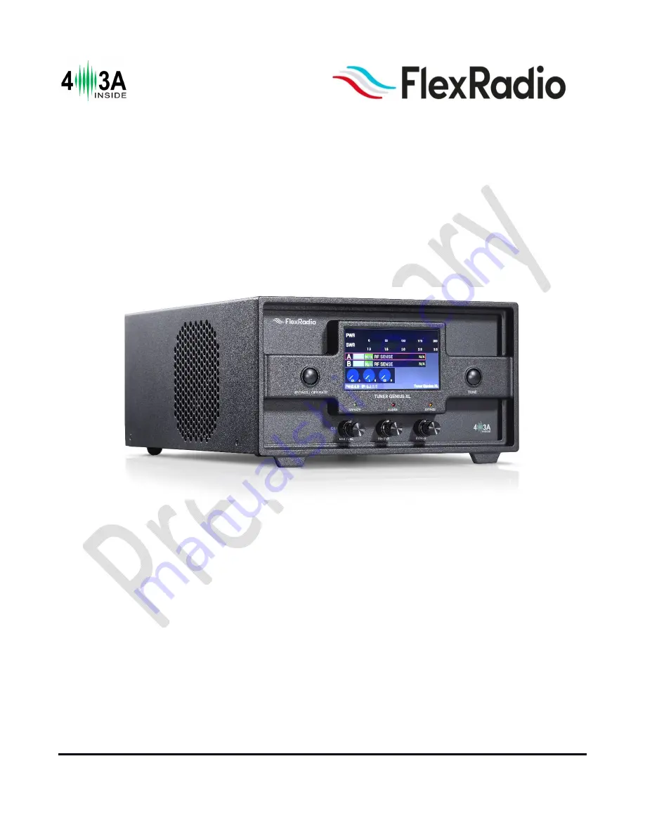
Tuner Genius XL 

User Guide 

(Preliminary) 


Tuner Genius XL Firmware Version 0.9.12 

Tuner Genius XL Windows Utility Version 0.9.12 

7 June 2021 


Summary of Contents for Tuner Genius XL

Page 1: ... registered trademark and SmartSDR is a trademark of FlexRadio All other brands or names are trademarks of their respective owners Tuner Genius XL User Guide Preliminary Tuner Genius XL Firmware Version 0 9 12 Tuner Genius XL Windows Utility Version 0 9 12 7 June 2021 ...

Page 2: ...1 2 SO2R Switch Model 15 6 1 3 All Models 15 6 2 Basic Configuration 19 6 2 1 Connecting the Tuner Genius XL Windows Utility program 19 6 2 2 Network Tab Set a Custom Device Name 21 6 2 3 Network Tab Configuring the Network 22 6 2 4 FlexRadio Tab Configuring for a FLEX 6000 Series Transceiver 24 6 3 Advanced Configuration 26 6 3 1 Required RF Output Delay TX Delay 26 6 3 2 Interfacing with Other E...

Page 3: ...7 4 4 Additional Information 52 8 The Tuner Genius XL Windows Utility 53 8 1 Tuner Chooser Screen 53 8 2 Windows Utility Front Panel Display 54 8 3 Tuner Configuration Dialog 54 8 3 1 Network Tab 55 8 3 2 CAT CI V Tab 57 8 3 3 FlexRadio Tab 57 8 3 4 Antenna Genius Tab 59 8 3 5 Other Tab 59 8 4 User Interface Elements 61 8 4 1 STBY Button 61 8 4 2 BYP Button 61 8 4 3 TUNE Button 61 8 4 4 Manual Tun...

Page 4: ...4 Firmware Recovery Proceedure 72 Table of Figures Figure 4 1 Tuner Genius Front Panel 9 Figure 4 2 Tuner Genius Front Panel Drawing 10 Figure 4 3 1x3 Antenna Switching Option 11 Figure 4 4 1x3 Switching Option Drawing 12 Figure 4 5 SO2R Switching Option 13 Figure 4 6 SO2R Switching Option Drawing 13 Figure 5 1 Basic 1x3 Connection Diagram 16 Figure 5 2 Basic SO2R Connection Diagram 16 Figure 5 3 ...

Page 5: ... or in indoor environments that exceed the designed environmental limits This unit is NOT A TOY It must not be handled by children nor placed operated within reach of children Do not leave packing material for this unit unattended It may be harmful to children if misused This unit contains small parts that could be a choking hazard to small children Do not leave accessories unattended Do not opera...

Page 6: ...any defect abnormal result or other observations occur that are not covered by this User Guide immediately cease operation and contact FlexRadio Support or local distributor for operational advice or repair of the unit i No physical modification of this tuner is allowed Any other use or modification including software changes that affect operational characteristics will void the manufacturer s war...

Page 7: ...ration is achieved using a standard LAN based API and communications protocol The API is published so you can write software applications for your tuner The Tuner Genius XL is compatible with any modern HF radio on the market today When used in conjunction with a Power Genius XL and a FLEX 6600 or FLEX 6700 transceiver you have a competitive fully functional SO2R single operator two radio radiospo...

Page 8: ...element of the matching network For each value the output of a directional coupler is sampled and used to search for a target impedance match Once a match solution is found the frequency and data necessary to recall the matching network s element values are stored in a non volatile memory location When the operator next transmits on a frequency within 10kHz of a stored solution the values required...

Page 9: ... Pin to Band PTB Legacy Exciter Interface Built in frequency counter PTT In and Out Open drain XXV and XXXma maximum Alarms Frequency out of range Wrong Band High Power SWR 10 1 Warnings Low drive PTT Unkey Messages Manual Tuning Tuning Saved Memory Cleared Config Reset 5 1 Front Panel Designed to be easy to use and intuitive the front panel consists of nine elements Figure 5 1 Tuner Genius Front ...

Page 10: ...June 2021 FW 0 9 12 Utility 0 9 12 Figure 5 2 Tuner Genius Front Panel Drawing 1 Bypass Operate button 2 Tune Button 3 4 5 110mm Color LCD Touchscreen Display 4 Manual Tune C1 Adjust 5 Minimum SWR L Adjust 6 Bypass C2 Adjust 7 Operate LED 8 Alarm LED 9 Bypass LED ...

Page 11: ... 1 1x3 Antenna Switching Option The 1x3 back panel option provides one input and three switchable antenna output connections The tuner will tune the signal on the input TX to the currently selected output ANT 1 2 and 3 Only the port A connections are active and the tuner can be controlled only by a single radio Figure 5 3 1x3 Antenna Switching Option ...

Page 12: ...emale connector for radio A band data 6 Ethernet connection RJ45 Local Area Network Ethernet connection 7 DC Power input Nominally 15 volts DC center pin positive 8 Main Power Switch 9 Station Ground B B inputs B inputs and output are intended for the SO2R switching option and are disabled for the 1x3 switching option 5 2 2 SO2R Antenna Switching Option The SO2R back panel option provides speciali...

Page 13: ... 12 Utility 0 9 12 Separate A and B keying inputs Push To Talk PTT and band data inputs are provided At any point in time either of the A or B sections can be keyed but they cannot be keyed simultaneously Figure 5 5 SO2R Switching Option Figure 5 6 SO2R Switching Option Drawing ...

Page 14: ...n of the tuner is keyed and ready to accept RF drive 2A B PTT Input Opto isolated female RCA connector Ground the center pin to shield to engage PTT for the A or B section of the tuner 3A B CI V Input Opto isolated 3 5mm female connector for Icom radio band data 4A B CAT Input Opto isolated male DB9 connector for radio CAT command input 5A B Band Data In Pin to Band or BCD 6 Ethernet connection RJ...

Page 15: ...diagrams to connect your Tuner Genius XL For connections to non FlexRadio products please see section 6 3 Advanced Configuration 6 1 1 1x3 Switch Model Connect the transceiver antenna output to the Port A TX socket on the tuner with a suitable 50 ohm coax jumper cable Connect an antenna to the ANT 1 antenna socket 6 1 2 SO2R Switch Model Connect the transceiver antenna output to the Port A TX sock...

Page 16: ... Utility 0 9 12 Figure 6 1 Basic 1x3 Connection Diagram The typical wiring configuration for the 1x3 tuner is shown in the diagram above The wiring for the SO2R tuner and using the tuner with the Power Genius XL is similar and depicted below Figure 6 2 Basic SO2R Connection Diagram ...

Page 17: ...Page 17 of 72 Copyright 2021 FlexRadio All Rights Reserved 7 June 2021 FW 0 9 12 Utility 0 9 12 Figure 6 3 SO2R Plus PGXL Connection Diagram ...

Page 18: ...r does not respond the tuner will self assign a Link Local IP Address following the RFC 3927 specification i If the displayed IP Address begins with 169 254 the tuner self assigned a Link Local IP Address Depending on your Local Area Network LAN configuration this may indicate a network problem and prevent further setup Contact FlexRadio Support for assistance When the start up sequence completes ...

Page 19: ...m It will automatically discover your Tuner Genius XL tuner and you should see something like this If you do not see your Tuner Genius XL in the Local devices list please Double check your network connections and cables Ensure the Tuner Genius XL is powered on and an IP address is displayed on the front panel Check that the PC s firewall is configured to allow the Tuner Genius XL Windows Utility t...

Page 20: ... the utility indicate it is connecting to the TGXL Once connected a tuner status screen will appear like the image below Next click on the configuration settings button outlined in red to open the tuner s configuration settings then continue to the next section of this document to set the tuner s basic configuration ...

Page 21: ...uner s front panel in the utility s Available devices list and the utility s main window Select the Network Tab on the Configuration screen Enter an appropriate name in the Device name field Click Save i The tuner will reset when Save is clicked i You do not need to click Save after every configuration change You can postpone it until you have completed all the configuration steps but you must cli...

Page 22: ...specific technical knowledge of the network Most configurations will not require these steps If you don t need any of these options please proceed to the next section The network settings screen performs basic validation of the network settings Note the red X next to an incorrectly formatted subnet mask below If you are not familiar with the rules of setting or using static IP addresses but believ...

Page 23: ...ns in section 10 Factory Reset the Tuner Genius XL Once you have pressed save the configuration dialog will close and the Tuner Genius XL Windows Utility will wait for the tuner to reset The utility will reconnect to the tuner when it appears on the network Before moving to the next step please click the configuration gear icon then select the Device settings menu item ...

Page 24: ...tup dialog as shown above If a FLEX 6000 transceiver is connected to Port B make the Port B configuration settings similarly It is not required that you connect ANT1 output on a FLEX 6000 series connect to Port A input on the tuner Any FLEX 6000 antenna output can be connected to any TGXL Port However it is required that the configuration match the physical connections TX Antenna This field config...

Page 25: ...number for both Port A and B sections on the configuration screen This configuration enables advanced Single Operator Two Radio SO2R operations using a single transceiver and tuner SO2R Configuration ANT2 Port A ANT1 Port B 1x3 pairing with the ANT1 output on a 6600M Click the Save button to record the configuration in the tuner The Tuner Genius XL tuner is now configured for use by the FLEX 6000 ...

Page 26: ...N keying a TX Delay value should be set to a minimum of 20 milliseconds to allow the tuner to select the correct tuning solution i A best practice is to create a Tuner Genius XL TX Profile for your FLEX 6000 Series transceiver and load that when using the Tuner Genius XL 6 3 1 2 TX Delay for Other Exciters When keying the tuner with other than FLEX 6000 Series transceivers you will need to use a r...

Page 27: ... tuner with band data information from exciters When the data arrives at the tuner over a CAT connection the frequency is provided to the tuner and the tuner records the tuning solution associated with the frequency Up to 20 solutions keyed by frequency can be stored for each band When the exciter does not provide data via a CAT connection but does provide band information via a BCD or Pin2Band co...

Page 28: ...band data and key the tuner it does not support multiple radios on a single tuner port 6 3 2 1 Elecraft The tuner requires both band data and a PTT line from Elecraft radios Band data is available using a custom wired BCD band decoder cable PTT Connect an appropriate cable RCA male terminated on both ends between the radio s Key output and the PTT Input corresponding to the tuner Port used A or B ...

Page 29: ...onfiguration To configure the tuner click on the CAT C IV tab in the Tuner Genius XL Configuration screen and check the Enable checkbox for the appropriate port Select the Kenwood CAT protocol the Radio type drop down menu for the tuner port Kenwood CAT protocol is effectively a generic protocol supported by many makes of transceivers Next select the serial communication port speed and configurati...

Page 30: ...ustom cable to access radio PTT from an accessory connector Please consult your manual for the correct PTT output Multi band radios may have more than one based on the band you are operating Below is an example using the REMOTE connector on a TS 2000 In this case pins 2 and 4 would be connected to the tuner s PTT IN on PORT A or PORT B Band Data CAT RS 232 CAT connections use a straight through fe...

Page 31: ...s XL Configuration screen Select Kenwood from the Radio type drop down menu for the tuner port where the radio is connected Next select the serial communication port speed and configuration parameters that apply to your radio Finally click the Save button to record the configuration in the tuner i The tuner will reset when save is pressed Please proceed to section 6 5 Testing ...

Page 32: ...he model PTT Connect an appropriate cable between the radio s PTT output and the PTT Input corresponding to the tuner Port A or B Some models may require a custom cable to access radio PTT from an accessory connector Create a custom cable connecting pins 2 GND and 3 SEND from the 8 pin DIN ACC 1 jack and a standard RCA plug from the PTT IN RCA jack Pin 3 connects to the center conductor of the RCA...

Page 33: ...d the CI V Input corresponding to the tuner Port used A or B Only two conductors are used tip and sleeve Three conductor CI V cables may be used and models may require a custom cable Please consult the user manual for your specific exciter CI V Patch Cable Connect the REMOTE output from the transceiver to the appropriate CI V Input A or CI V Input B connector on your Tuner Genius XL ...

Page 34: ...the hexadecimal value of the CI V address configured for your Icom transceiver Here are some common default values as examples although any value from 00 to FF can be used Icom Model Default CI V Hexadecimal Address IC 775 46 IC 7000 70 IC 7800 6A 1 Change the CI V address of the Icom radio to the value currently configured in your transceiver 2 Connect a PTT cable between the radio and the approp...

Page 35: ...DIN connector PTT Connect an appropriate cable between the radio s PTT output and the PTT Input corresponding to the tuner Port A or B Some models may require a custom cable to access radio PTT from an accessory connector Band Data CAT RS 232 CAT connections use a straight through female to female DB9 cable You can connect either the CAT Input A or CAT Input B connector on your tuner to the CAT co...

Page 36: ... connector on the Yaesu transceiver to the Band Data A or Band Data B DB15 connector on the tuner The restriction described in section 6 3 1 4 Band Data and Frequency Measurement based restrictions applies in this case BCD connections use a custom cable configured as shown in this diagram i Optocouplers protect all serial and digital inputs or outputs on the Tuner Genius XL ...

Page 37: ...l configuration is required for BCD mode The tuner will detect the presence of a BCD or Pin to Band interface Click on the CAT C IV tab in the Tuner Genius XL Configuration screen Click the Save button to record the configuration in the tuner i The tuner will reset when save is pressed Please proceed to section 6 5 Testing ...

Page 38: ...Input B connector on the tuner This connection requires no additional configuration and works automatically Band data arriving on the BCD PTB connection overrides other sources See section 14 2 7 PTB BCD Connector Pinout for additional information Also see section 6 3 1 4 Band Data and Frequency Measurement based restrictions in this case CAT protocol Connect your radio s CAT output to the CAT Inp...

Page 39: ...and the 1x3 version does not support inputs from more than one amplifier The tuner requires both band data and a PTT line when using amplifiers 6 3 4 1 PTT PTT is easy to provide generally requiring a single two conductor cable However almost all amplifiers require exciters that drive them to delay emitting RF until the amplifier is ready to amplify it The Tuner genius also requires a short delay ...

Page 40: ...Page 40 of 72 Copyright 2021 FlexRadio All Rights Reserved 7 June 2021 FW 0 9 12 Utility 0 9 12 6 3 4 5 ACOM TBD Please proceed to section 6 5 Testing ...

Page 41: ...or on the tuner This connection requires no additional configuration and works automatically Band data arriving on the BCD PTB connection overrides other sources See section 14 2 7 PTB BCD Connector Pinout for additional information The restriction described in section 6 3 1 4 Band Data and Frequency Measurement based restrictions may apply CAT protocol Connect your radio s CAT output to the CAT I...

Page 42: ... Genius AG will unlock additional solution memories in the Tuner Genius XL and automatically switch to an appropriate antenna for the frequency or band you are using 6 4 1 Enable Integration To enable AG integration you must enable it supply the network TCP IP address and TCP port used by the Antenna Genius on the Antenna Genius tab of the Tuner Genius XL Windows Utility For example in the case be...

Page 43: ...y 0 9 12 6 4 2 Using the Antenna Genius User Interface Once the integration step is performed the Tuner Genius XL and Antenna Genius will follow the band or frequency used by the exciter You may use the Antenna Genius application to switch antennas if configured for the band you are using ...

Page 44: ...r Band The Tuner Genius XL will add up to four Antenna Genius antenna slots per band and appropriately change the Band Configuration dialog This powerful advanced but easy to use feature allows you to configure how the Tuner Genius XL manages multiple antennas Each antenna slot per band is capable of 20 frequency memories ...

Page 45: ...L Windows Utility for the port you have chosen Make sure all RF connections are correctly attached and tightened and that an appropriate antenna or dummy load is attached to the appropriate tuner output Change to another band and verify the tuner follows the change Set the drive power at the transmitter to about 20 watts and transmit a carrier The tuner should switch into transmit mode The PTT ind...

Page 46: ...ghts Reserved 7 June 2021 FW 0 9 12 Utility 0 9 12 The tuner status screen will appear as shown below Next click on the configuration settings button outlined in red to open the tuner s configuration settings dialog window SO2R Version 1x3 Version ...

Page 47: ...2 By changing the mode using software such as the utility program Front panel Hard button Tuner Genius XL Windows Utility Button i When properly configured a convenient method for switching between Standby Operate and Bypass modes use software connected to the Tuner Genius XL over the LAN The front panel BYPASS OPERATE button and the utility s BYP button toggle the operational state between Bypass...

Page 48: ... is found the match solution L C L values and frequency is retained in tuner non volatile memory and automatically used when the frequency of the transmit slice is within the Match Frequency Range with the same antenna selected 7 3 What is a successful match The Tuner Genius XL tries different combinations of capacitance and inductance values during automatic tuning until it finds a combination th...

Page 49: ...Page 49 of 72 Copyright 2021 FlexRadio All Rights Reserved 7 June 2021 FW 0 9 12 Utility 0 9 12 7 3 1 Automatic Tuning ...

Page 50: ... leftmost knob to select manual tuning The Manual Tuning message appears on the front panel display Adjust the knob to select the first capacitance Adjust the middle knob to select the inductance Adjust the rightmost knob to select the final capacitance Press the leftmost knob to save the result for later use In many cases two or more values of the inductance may produce minimum SWR values The gen...

Page 51: ...s the transmitted peak and average power It ranges from 0 to 2000 watts In addition a maximum power indicator is shown when demanded by the limits of the tuning solution i Power measurements update approximately every 100ms and should be used for reference only For a more accurate power reading transmit a fixed amplitude and frequency signal for at least 1 second 7 4 2 SWR meter The SWR meter show...

Page 52: ...his label background is red when PTT is detected 3 Band Indicator Displays the selected band 4 Frequency Source and Frequency Displays the current frequency source and frequency When no band data is present this label displays RF SENSE indicating the port will sense the RF frequency when the signal arrives 5 Antenna Genius Antenna Port Displays 1 8 or of not present 6 Bypass or Operate 7 4 4 Addit...

Page 53: ... Local Devices tab shows a list of tuners available in your local area network LAN Click on a tuner to select it then click the Connect button to display the tuner The Remote Devices tab shows a list of remote tuners that have been configured for use by the utility program Click on a remote tuner to select it then click the Connect button to display the tuner To add a remote tuner to the list clic...

Page 54: ... button that displays version information for the program and buttons that minimize and close the display The red outline box indicates the tuning solution that is currently applied 8 3 Tuner Configuration Dialog Clicking the Configuration button gear icon at the top right of the Tuner Genius XL Windows Utility screen produces a menu of three selections 1 Always on Top 2 Device settings 3 Upgrade ...

Page 55: ...ts creating a custom Device Name for a tuner This name is simply a short text string that is associated with a specific tuner It can be set changed and cleared on the Network tab of the Configuration screen as shown below In this case the user has set the nickname to N7HQ TGXL As a result the nickname will appear in the utility program s chooser as shown below and in the title bar of the utility p...

Page 56: ... 3 Network Tab Configuring the Network for details 8 3 1 3 Remote access The Tuner Genius XL can be controlled remotely with the Tuner Genius XL Windows Utility program by setting an authorization code in the field shown above The value entered here is effectively a password that allows access to the program from a non local area network such as the Internet See section xxx for information about m...

Page 57: ...ceiver s make and model connected to each of the tuner ports and the details of the communication protocol between the radio and the tuner A selection of radio makes and models are provided Do not use this tab to configure FLEX 6000 Series transceivers Click the Save button after the choices have been made 8 3 3 FlexRadio Tab Figure 8 1 A FLEX 6600M configured for operations on Port A and ANT 1 on...

Page 58: ...osts the Tuner Genius XL The Tuner Genius XL Windows Utility will discover the FLEX 6000 Series transceivers over the network You must select the serial number of the radio connected to each port Leave the serial number field blank if you do not want that port paired with a FLEX 6000 Series transceiver Select the antenna port from the FLEX radio ANT1 or ANT2 connected to the tuner port A or B Be s...

Page 59: ...nna Genius device downstream of the tuner First enter the IP address and Port that the Antenna Genius uses 8 3 5 Other Tab Use the Other tab to adjust the front panel backlight intensity set the per band bypass configuration and the receive mode bypasses Display Backlight Intensity This control sets the brightness of the front panel display Click Save to make a change permanent ...

Page 60: ... case frequencies near this value can be bypassed by selecting the Enable Bypass check box in the 80M row then enter the range of the bypass in the Bypass Start and Bypass Stop columns Note the use of KHz in these columns The Port B tab is only valid for the SO2R switching model Minimal SWR The Minimal SWR value is used as a target by the tuner solution algorithm This feature gives the operator so...

Page 61: ... Bypass Start and Bypass Sop a tuning solution will always be applied 8 4 User Interface Elements 8 4 1 STBY Button The utility application provides a standby bypass button Clicking this button changes the tuner from Standby mode to Operate or Bypass mode and back 8 4 2 BYP Button The utility application provides a bypass operate button Clicking this button changes the tuner from Bypass mode to Op...

Page 62: ...the Tuner Genius XL Windows Utility display show the current tuning solution C L C These can be adjusted manually by clicking on the leftmost knob and adjusting the value with the mouse wheel Then click on the knob again to save the value The middle and rightmost knobs can be adjusted in the same way See section 7 3 2 Manual Tuning for more information ...

Page 63: ... 2 Click the UPGRADE button to start the firmware upgrade process The TGXL microprocessor will enter the boot loader The firmware image will be transferred over the network to the tuner The tuner will reboot When the firmware transfer is complete a status dialog will be shown 3 Click the OK button to close the notification dialog 4 Close the Firmware Upgrade dialog by clicking the X in the top rig...

Page 64: ...w settings will not be retained and you will have to rerun the reset procedure 11 Alarms Warnings and Messages If the tuner detects an operational error a message is displayed on the main display and on the Windows Utility as shown below 11 1Alarms When an alarm is raised the tuner bypasses to protect itself from damage The alarm is cleared when the PTT is released Alarm Description FREQUENCY OUT ...

Page 65: ...of 72 Copyright 2021 FlexRadio All Rights Reserved 7 June 2021 FW 0 9 12 Utility 0 9 12 Message Description MANUAL TUNING Lorem ipsum TUNING SAVED Lorem ipsum MEMORY CLEARED Lorem ipsum CONFIG RESET Lorem ipsum ...

Page 66: ...ment 10W 200W RF Power 2000W maximum Exciter Inputs 2 SO 239 Antenna Outputs 2 SO 239 Antenna Impedance 50 ohms unbalanced Cooling Thermostatically Controlled Fans Mechanical Specifications Dimensions 11 8 W x 13 8 D x 5 9 H 30cm W x 35cm D x 15cm H Weight 15 4 pounds 7 kg Operating Temperature 4 F 20 C to 122 F 50 C Electrical Specifications Supply Voltage and Current 12 16V DC 2A 13 FCC Statemen...

Page 67: ...s used to configure the tuner upgrade the tuner s firmware and operate it remotely Download the installer for the program from the FlexRadio website and install the program on a Windows PC located on the same local area network LAN as the tuner The installer can be found in the software section of the FlexRadio website https www flexradio com category tuner genius xl You will be presented with a d...

Page 68: ... s firewall needed by the utility program to communicate with the tuner You can choose to allow the application to function on Private Networks Public Networks or both network types Click Allow access to complete the installation i Windows Updates have in the past changed the network type from Private to Public without warning Therefore if your PC is not a laptop you travel with a best practice is...

Page 69: ...ided for an external Push To Talk signal Ground the center pin to engage PTT Note 3 3VDC Max Input 14 2 3 2 PTT OUT This RCA connector is provided to supply a Push To Talk signal to other devices The center pin is grounded when PTT is asserted Note that the Tuner Genius XL provides this signal after making any adjustments to the tuning solution when it receives PTT This signal can therefore be use...

Page 70: ...logic TTL level serial interface that allows more than one device daisy chained or on a bus Each device is required to have a unique CI V address The TGXL uses two CI V signal lines data tip and ground sleeve it does not implement the PTT RTS line on the ring 14 2 6 LAN Ethernet Connector This RJ45 jack is the Ethernet network connection for the radio It is an auto sensing 10 100 megabit Ethernet ...

Page 71: ...gnal Ground i The 60 meter band cannot be selected with this method BCD input A 4 bit BCD signal 5 to 15 volt DC selects a band The pins are opto isolated Pin 15 is the signal ground The BCD inputs are designed for connection directly to a band decoder output provided by radios such as Yaesu and Elecraft Band 160m 80m 40m 30m 20m 17m 15m 12m 10m 6m None Frequency MHz 1 8 3 5 7 10 14 18 21 24 28 50...

Page 72: ...n the TGXL 5 Hold the OPERATE BYPASS button on the front of the TGXL down 6 Turn ON the TGXL 7 Release the OPERATE BYPASS button 8 The TGXL will show a bootloader version and IP address 192 168 1 250 on the front panel 9 Start the TGXL Windows Utility do not connect to your TGXL 10 Click the gear Icon on the titlebar of the TGXL Windows Utility 11 Select Upgrade Firmware 12 The Utility should now ...

Reviews: