background image

922-MFC

Installation and Operating Instructions

99651 02/02/06

Summary of Contents for 922-MFC

Page 1: ...922 MFC Installation and Operating Instructions 99651 02 02 06 ...

Page 2: ...oards must be transported in a con ductive bag or other conductive container Boards must not be removed from protective enclosure until the imme diate time of installation Removed boards must be placed immediately in protective container for transport storage or return to factory Comments This instrument is not unique in its content of EDS elec trostatic discharge sensitive components Most modern ...

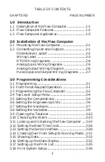
Page 3: ...0 Programming Considerations 3 1 Programming 3 1 3 2 Front Panel Keypad Operation 3 1 3 3 Programming the Flow Computer 3 2 3 4 Top Level Setup Menu 3 4 3 5 Setting the Computations 3 4 3 6 Setting the Engineering Units 3 6 3 7 Setting the Hardware 3 7 3 8 Setting the Variables 3 9 3 9 Clearing the Totalizer 3 22 3 10 Checking the Alarm 3 23 3 11 Locking and Unlocking the Flow Computer 3 24 3 12 S...

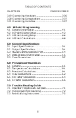
Page 4: ...l Specifications 5 1 Input Specifications 5 1 5 2 Output Specifications 5 1 5 3 RS232 Communications Port 5 4 5 4 Data Display and Keypad 5 6 5 5 Case Dimensions 5 7 6 0 Principles of Operation 6 1 General 6 1 6 2 Temperature Calculations 6 1 6 3 Pressure Calculations 6 1 6 4 Flow Calculations 6 2 6 5 K1 Factor Calculation 6 4 6 6 C Factor Calculation 6 6 7 0 Trouble Shooting Guide 7 1 Operator Fo...

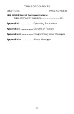
Page 5: ...S CHAPTERS PAGE NUMBER 8 0 RS232 Serial Communications Table of Chapter Contents 8 1 Appendix i Operating Parameters Appendix ii Conversion Factors Appendix iii Programming Error Messages Appendix iv Alarm Messages iv ...

Page 6: ...s powered by 50 or 60 Hz 110 or 220 VAC switch selectable or can be ordered for 12 or 24 VDC power The Flow Computer is designed to provide continuous on line compensation for true flow rate from volumetric flow transducers All volumetric mass or heat flow calcula tions are taken with permission from the Flow Measure ment Engineering Handbook written by R W Miller Steam 100 quality saturated or su...

Page 7: ... flow as well as totalized flow with an overall accuracy of 0 25 over commonly required application ranges Fully programmable from the front keypad the micropro cessor based Flow Computer provides the operator with prompts to set up the operating parameters of the instru ment The Flow Computer offers the following features Front panel 16 key programming keypad 2 line by 20 character backlit LCD di...

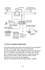
Page 8: ...ow Computer Turbine flowmeter sends digital signal to Flow Computer Flow Computer calculates flow and sends out signals 5 V pulse out to remote totalizer in supervisory area 4 20 mA out to strip chart recorder tracks trends RS232 out to printer for data logging Alarm relays activate bell and or light as needed 1 3 ...

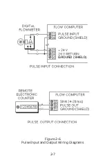
Page 9: ...ckets and insert in the slots located on all four sides of the instrument Tighten the screws to firmly secure the bezel and gasket up against the panel CAUTION do not over tighten mounting brackets 2 2 Connecting Inputs and Outputs Make sure all power is disconnected before making any electrical connections All connections are completed at the rear terminal strips as indicated in the external wiri...

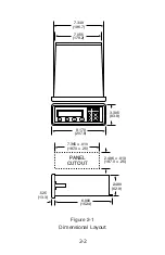
Page 10: ...2 2 Figure 2 1 Dimensional Layout A B C D 1 2 3 4 5 6 7 8 9 CLR 0 SET 8 170 207 5 3 305 83 9 525 13 3 6 000 152 4 2 480 62 9 PANEL CUTOUT 2 496 010 187 0 25 7 365 010 187 0 25 7 055 179 2 7 349 186 7 ...

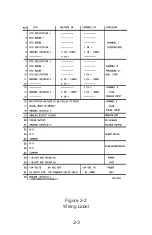
Page 11: ...2 3 Figure 2 2 Wiring Label ...

Page 12: ...EXCITATION RTD SENSE RTD SENSE RTD EXCITATION GROUND SHIELD 2 WIRE CONNECTION RTD EXCITATION RTD SENSE RTD SENSE RTD EXCITATION GROUND SHIELD 3 WIRE CONNECTION RTD EXCITATION RTD SENSE RTD SENSE RTD EXCITATION GROUND SHIELD 4 WIRE CONNECTION ...

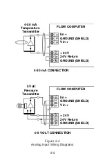
Page 13: ...mperature Transmitter 4 5 6 30 3132 1112 10 30 3132 5 Volt Pressure Transmitter FLOW COMPUTER FLOW COMPUTER I in GROUND SHIELD V in 24 V 24 V Return GROUND SHIELD I in GROUND SHIELD V in 24 V 24 V Return GROUND SHIELD 4 20 mA CONNECTION 0 5 VOLT CONNECTION ...

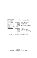
Page 14: ...2 6 Figure 2 5 Analog Output Wiring Diagram GROUND SHIELD ...

Page 15: ...2 7 Figure 2 6 Pulse Input and Output Wiring Diagrams GROUND SHIELD ...

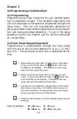
Page 16: ...beled 0 9 A B C D ENT and CLR The functions of each one is described as fol lows A Advances to the next item in the menu or sub menu If you are at the last item the A button will have no effect on the display The display will not wrap around to the top of the menu B Backs up to the previous item in the menu or sub menu If you are at the first item the B button will have no effect on the display Th...

Page 17: ... no value to be displayed Upon entry the unit will advance automatically to the next menu item 3 3 Programming the Flow Computer The software in the instrument contains a number of menus This allows the setting of the various operating parameters in the instrument You should become famil iar with the function keys located on the front of the in strument before you program the Flow Computer Before ...

Page 18: ... B A B A B A B A B A B A B A B A B A B A B A B A B A B Press ENT to enter the selected menu subroutine Press C cancel at any time to return to the Run or Go to standby prompt Run allows you to cross over from Setup to Run Go to standby allows you to cross over from Run to Setup When in Standby mode you can Setup and change the operating parameters of the instrument When in Run mode you can Examine...

Page 19: ...o move through the Top Level Setup Menu Press the C button to jump to the top of the menu Under each menu there are sub menus The instrument will prompt you for various bits of information and deci sions 3 5 Setting the Computation The computations are the formulas that are used by the software to process the raw data into meaningful informa tion Chapter 6 goes into detail about the formulas used ...

Page 20: ...e resulting flow is dis played in lbm h kg h and totalled in lbm kg Unit may be set up to follow saturated steam curve see page 3 12 Steam tables are satu rated 1 psia to 3200 psia with superheated values up to 900 F Higher temperatures cause an alarm condition Liquids Mass Uses volume and temperature to yield a compen sated Mass flow The resulting flow is displayed in lbm min kg h and totalled in...

Page 21: ...id Uses volume and temperature to yield a compen sated Mass flow as well as Heat flow The resulting Heat flow is displayed in Btu h kW kcal h MJ h and totalled in kBtu kWh kcal MJ Del Heat Liquids Uses volume and two temperatures to yield a compensated Mass flow as well as Heat flow The resulting Heat flow is displayed in Btu h kW kcal h MJ h and totalled in kBtu kWh kcal MJ 3 6 Setting the Engine...

Page 22: ...ppendix i bar Metric Temperature C Pressure bar Other data as de scribed in Appendix i 3 7 Setting the Hardware The hardware selection determines from which input ter minals the unit will get its raw data There are no dip switches or cards to change to go from one type of input to another Internal analog switches activate the proper terminals for the input type selected Review the specifi cation s...

Page 23: ...e Flow input type ENT A B Prompt Selections Set Hardware Input Configuration Pressure Input type or Input Configuration Temperature two Flowmeter type Linear Orifice Pitot Input type Sixteen Point 5 Volts 10 Volts 0 20 mA 4 20 mA Prompt Selections RTD 100 Ohm 5 Volts 10 Volts 0 20 mA 4 20 mA Prompt Selections A A B Input Configuration Temperature Input type RTD 100 Ohm 5 Volts 10 Volts 0 20 mA 4 2...

Page 24: ...pressure This type is not available when Digital Pulse is selected as the input type Sixteen point is for compensating any other type of non linear input signals that represent volumetric flow Be sure that input devices are wired to the proper terminals If Hardware selection does not match wiring the result will be er roneous readings 3 8 Setting the Variables The variables will determine how the ...

Page 25: ...B C or ENT In the same manner that you set the Computations and the Hardware you will set the variables for the instru ment Use the numeric keypad to input the desired variables for the instrument in the Variable menu The D key sets the decimal point when entering a numerical value The example below shows how to enter the value of 256 58 PSIG At input minimum Lo press 2 5 6 D 5 8 ENT The D key ins...

Page 26: ...nu is replaced by a second tempera ture sub menu if the Del Heat Liquids computation is selected See Setting the Temperature Variables The pressure input is not required for Liquids Mass or Volume computations The functionality of the inputs and sub menu remain active and can be used if desired Graphical representation of the Pressure sub menu 3 11 Pressure input At input minimum Lo press At input...

Page 27: ...ture and no pressure input use one of these two methods 1 Set Lo press 0 00 and Hi press 0 00 The Flow computer will use the temperature input to look up the corresponding pressure on the saturated steam table for calculations and display 2 Set Lo temp 0 00 and Hi temp 0 00 The Flow computer will use the pressure input to look up the corresponding temperature on the saturated steam table for calcu...

Page 28: ... Scale Fac tor High Temperature Scale Factor Low Temperature Limit High Temperature Limit A leading minus sign may be entered by pressing the zero 0 key as the first keystroke when entering any of these values Subsequent strokes of the zero key will result in zeroes being entered into the number as usual The zero key will act conventionally for data entry of any other variable Graphical representa...

Page 29: ...low sub menu varies with the computation or hardware selections you have previously made There are 45 different combinations of hardware and com putation settings General menus will be given in this manual All variables will be shown Be sure to observe notes as to which variables will be used in your situation SIXTEEN POINT The setup procedure for the Sixteen Point sub menu is covered in Chapter 4...

Page 30: ... 3 Used in Liquids equations only 4 Used in Gas Heat Liquid Heat and Liquid Del Heat equations only Flow input Notes Pulses per unit vol K factor Gas compressibility 1 Z factor Specific gravity 2 Gravity Thermal Expansion 3 C x 10E 6 Mean 4 Spec Heat Cutoff 0 to 40000 Hz Input filter Flow alarm setpoint Lo alarm Flow alarm setpoint Hi alarm p p p p p ENT p p p A B A B A B A B A B A B A B ...

Page 31: ...uations 3 Used in Liquids equations only 4 Used in Gas Heat Liquid Heat and Liquid Del Heat equations only Flow input Notes Gas compressibility 1 Z factor Specific gravity 2 Gravity Thermal Expansion 3 C x 10E 6 Mean 4 Spec Heat Cutoff 0 to 40000 Hz Input filter Flow alarm setpoint Lo alarm Flow alarm setpoint Hi alarm p p p p p ENT p p p Linearize 16 Point A B A B A B A B A B A B A B ...

Page 32: ...d in Liquids equations only 4 Used in Gas Heat Liquid Heat and Liquid Del Heat equations only Flow input Notes Gas compressibility 1 Z factor Specific gravity 2 Gravity Thermal Expansion 3 C x 10E 6 Mean 4 Spec Heat Flow alarm setpoint Lo alarm Flow alarm setpoint Hi alarm p A B p p p p ENT p p p At input minimum Lo flow Low flow Cutoff At input maximum Hi flow p A B A B A B A B A B A B A B ...

Page 33: ...only 4 Used in Gas Heat Liquid Heat and Liquid Del Heat equations only Flow input Notes Gas compressibility 1 Z factor Specific gravity 2 Gravity Thermal Expansion 3 C x 10E 6 Mean 4 Spec Heat Flow alarm setpoint Lo alarm Flow alarm setpoint Hi alarm p A B p p p p ENT p p p At input minimum Delta P lo Low flow Cutoff At input maximum Delta P hi p A B A B A B A B A B A B A B Meter compensation fact...

Page 34: ...ds equations only 4 Used in Gas Heat Liquid Heat and Liquid Del Heat equations only Flow input Notes Gas compressibility 1 Z factor Specific gravity 2 Gravity Thermal Expansion 3 C x 10E 6 Mean 4 Spec Heat Flow alarm setpoint Lo alarm Flow alarm setpoint Hi alarm p A B p p p p ENT p p p At input minimum Lo flow Low flow Cutoff At input maximum Hi flow p A B A B A B A B A B A B A B p Linearize 16 P...

Page 35: ...lue or differential pressure value for Linear or Orifice Pitot measurement respectively at which the analog value input is highest Lo flow Cutoff Lowest uncompensated flow value below which any calculations are unnecessary For Example i A small leakage when valve is closed to be ignored ii Inaccuracy at lowest end of square law measurements C factor x 10 6 Thermal coefficient of expansion for liqu...

Page 36: ...low 20mA The compensated flow rate value to be repre sented by the 20 mA end of the 4 to 20 mA output 4 20 mA Example 4 mA 10 20 mA 1000 The Flow Computer will sink 4 mA from a flow rate of 0 to 10 Then it will linearly ramp up to 20 mA as the flow increases to 1000 The current will clamp at 20mA even though the flow may exceed 1000 until the flow drops back into the active range Digital pulse out...

Page 37: ...ntarily then the menu advances to Check Alarm Check Alarm On the RUNNING side of the menu you have an other opportunity to clear the totalizer DISPLAY PRESS Running Show Data A Running Go To Standby A Running Setup Data Display A Running Setup print list A Running Print system setup A Running Clear Totalizer ENT The words Totalizer Cleared are displayed mo mentarily then the menu returns to Runnin...

Page 38: ...u will return to Running Show Data If the alarm should go off anytime during the Stand by or Running modes of the Flow Computer you can easily check which point has most recently gone into alarm by following these menu steps DISPLAY PRESS Run A Set Computations A Continue Pressing A until Clear Totalizer A Check Alarm ENT Alarm Condition Shown Press ENT to quiet This procedure will have to be comp...

Page 39: ... A Set Computations A Engineering Units A Continue Pressing A until Check Alarm A Lock Unlock ENT Machine is unlocked You enter a Enter code 5 digit 1 2 3 4 5 code number Machine is unlocked NOTE Code number Enter code may be any number except 00000 Machine is unlocked Re enter 5 digit Now confirm code 1 2 3 4 5 number Machine is unlocked After confirming Now Confirm Flow Computer will revert to m...

Page 40: ...unlock the machine from the RUNNING side of the menu DISPLAY PRESS Running Show Data A Running Go To Standby A Continue Pressing A until Running Alarm Check A Running Lock Unlock ENT Follow procedure on previous page If you lock yourself out of the Flow computer and you have forgotten the security code access can be gained by entering a security code of 00000 The Flow Computer will prompt you with...

Page 41: ...his reason if you are using this feature the time and date must be reset upon each power up To do this follow the menu listed below DISPLAY PRESS Run A Set Computations A Continue Pressing A until Check Alarm A Real time clock ENT Select Item Set Time ENT Enter time hr min i e 14 32 Enter time hr min 14 32 ENT Remember that when entering the time for the real time clock it must be in 24 hour forma...

Page 42: ...me clock ENT Select item Set Time A Select item Set Date ENT Enter date mo da yr i e 2 16 90 Enter date mo da yr 2 16 90 ENT Entering an invalid time or date will cause an error message to be displayed Such as Bad Time value or Bad Date value Push ENT to continue After entering the date the menu will advance to Serial interface Set Date Month 01 to 12 Day 01 to 31 and Year 00 to 99 3 27 ...

Page 43: ... unit with a unique whole number between 1 and 99 To set the Unit Identification Number follow the menu shown below DISPLAY PRESS Run A Set Computations A Continue Pressing A until Real time clock A Serial Interface ENT Serial Interface Unit ID ENT 1 99 Unit ID i e 3 Entering an invalid ID number will cause the following error message to be displayed Bad ID value Push ENT to continue Display advan...

Page 44: ...y cause an undesirable delay in access This is especially true when the print list is lengthy Display advances to next menu item when ENT is pressed The next item is the Print Interval DISPLAY PRESS Serial Interface Baud Rate A Serial Interface Print Interval ENT The Print Interval is the time between automatic print outs For more information on the Print Interval see Chapter 8 in minutes Print in...

Page 45: ...e On Off Line ENT On Off Line Off A B On Off Line On The option to print out alarm conditions automatically when they occur is also available on units with the RS232 option This menu directly follows the On Off Line selec tion DISPLAY PRESS Serial Interface On Off Line A Serial Interface Exception Reporting ENT Graphical representation of the Exception Reporting sub menu Serial Interface Exception...

Page 46: ...rameter values out the serial port Used to reset Totalizer to 0 0 Used to review how hardware has been configured Used to review which machine formulas have been selected Used to review how input variables have been configured Used to see most recent alarm condition Used to access and change the machine function Running Show Data Running Go To Standby Running Setup Data Display Running Setup Print...

Page 47: ...nt operating data such as flow rate temperature or pressure The following data can be scanned and displayed on the front panel of the instru ment 1 Time Date Current Time and Date 2 Flow Rate In rate units per minute or hour 3 Mass Flow In mass flow units per minute or hour 4 Heat Flow In heat flow units per minute or hour 5 Totalizer Flow Compensated accumulated flow 6 Totalizer Mass Compensated ...

Page 48: ... 19 Flow Frequency Raw pulse frequency in The operator can designate the items of this list that will be displayed and in which order they will be displayed Each item will be displayed about two seconds Addition ally each point can be displayed more than once in the scan list If you find that a parameter is not being dis played long enough select it twice in a row Note The parameters available for...

Page 49: ... These variables are listed above Select Item 1 Mass Flow ENT Pressing the enter key selects that item for display The Item will increment as selections are made Continue to advance or backup through the list of available items making selections as you go along Select Item 2 Totalizer ENT Select Item 3 Temperature C Pressing the C button exits from the routine back to Show Data ...

Page 50: ...ng this Use a similar procedure as that used for the display list to set up the list of items that you would like to data log while the machine is running Select the items by pressing the ENT key while it is displayed you can select the items you desire For ex ample DISPLAY PRESS Select Item 1 ENT Flow Rate Select Item 2 ENT Totalizer Select Item 3 A Temperature Select Item 3 ENT Pressure Continue...

Page 51: ...he RS232 se rial communications port is performed 3 19 Examine Hardware In the running mode parameters cannot be changed but they may be viewed This is done by using one of the Examine menus Examine Hardware Examine Comps and Examine Variables This feature is used to examine the hardware setup con figuration of the unit Operation is as follows DISPLAY PRESS Running Show Data A Continue Pressing A ...

Page 52: ...mps ENT Once selected use ENT key to return to Show Data 3 21 Examine Variables This feature is used to examine the various parameters and constants that have been entered DISPLAY PRESS Running Show Data A Continue Pressing A until Running Examine Comps A Running Examine Variables ENT Once selected use A B and ENT keys to scroll through the parameters setup Use the C key to return to Show Data 3 3...

Page 53: ...sumes there are no more points above the points that preceded them Extrapola tion is taken from the last two non zero points 3 If the input frequency is above the highest or below the lowest frequency programmed the unit will use the last two points to extrapolate what the K factor should be and the resulting actual flow Care must be taken that the K factor does not extrapolate to zero If this hap...

Page 54: ... Continually press A until Set Variables ENT Once in the Variables menu advance to the Flow input sub menu Pressure input A Temperature input A Flow input ENT Linearize 16 Point ENT Enter Point Freq01 Data entry can now begin Using the A and B keys you can advance or backup to any one of the 16 points It is suggested that you start with point 01 and work your way up through the points The K Factor...

Page 55: ...rmined and K factors derived Below is some sample data that compensates for some low end inaccuracies This sample is an illustrative example applicable to a gas application using English units Sample Data Input Actual ft3 sec Frequency Actual flow K factor 0 0 1 0000 10 8 1 2500 20 18 1 1111 30 29 5 1 0170 100 100 1 0000 1000 1000 1 0000 The data would be entered as follows Display shows Press Ent...

Page 56: ... 1000 Hz will be modified by a K factor of 1 4 3 16 Point Analog Setup Analog programming is same as the Digital setup The Flow Computer asks for 16 different flow rates and 16 corresponding K factors correction factors It then uses this data to determine what the true flow is for any given actual apparent input signal Again a minimum of three points must be set up K factor Actual Input Flow True ...

Page 57: ...16 Point ENT The data would be entered as follows Enter Point Actual01 00 Actual01 0 0000 K Factor01 1 Enter Point Actual02 10 etc The Flow Computer prompts you for the actual input sig nal and a K factor to divide it by to yield true actual flow i e 16 Point corrected ACFM The actual apparent flow has assumed units as follows Flow Equation English Metric gas steam Actual ft3 min Actual M3 hr liqu...

Page 58: ...ine closest point above input signal signal X K factor KA Determine closest point below input signal signal Y K factor KB Let input signal H unknown K factor KN To find KN use this formula H Y X Y For example Using the values given earlier with an input frequency of H 15 Hz yields Determine closest point above input signal signal 20 Hz K factor KA 1 1111 Determine closest point below input signal ...

Page 59: ...t Specifications The following applies to all inputs in all modes Inputs are referenced to the signal ground All ground terminals are connected internally The exception is the RTD input which is differential but is referenced to ground Transient protection 100V 5nsec Note In the event of the specified fault conditions unit may temporarily malfunction but no perma nent damage will occur 5 11 Analog...

Page 60: ...3 760 Calibration Suitable for use with 2 3 or 4 wire RTD s Excitation Current 2mA typical Max Fault Current 15mA Max Voltage on sense inputs 50 VDC Rejection of 50 or 60Hz signal 40dB minimum Automatically based on line frequency Raw Accuracy 0 5C Temperature Range 323 5 to 1378 7 F 197 5 to 748 1 C Lead Wire Compensation 4 Wire Four wire field wiring required for 2 3 and 4 wire RTD s See schemat...

Page 61: ...lse width 10µsec with 40kHz filter Thresholds OFF is less than 2 0V ON is greater than 2 5V Input Impedance 40KΩ to ground minimum Excitation Voltage 5VDC through 5 6KΩ resistor Min Frequency to maintain rate display 5 Hz Typical Digital Pulse Input Schematic 5 3 2 mA Excitation Current Output 20 KΩ 20 KΩ 100 KΩ 1 5 uF 1 5 uF A D 5 VDC 0 9 mA 5 6 K Ω 39 K Ω 100 K Ω 5 VDC 5 VDC Counter ...

Page 62: ...ut This output is intended to drive a counter with a minimum input impedance of 1000Ω It is also compatible with TTL LSTTL and 5V CMOS logic inputs It is slew rate limited to help reduce RFI Number 1 Output High Voltage No load 4 5 Volts min 4 0 mA source 4 0 Volts min Output Low Voltage No Load 0 2 Volts max 4 0 mA sink 1 0 Volts max Output waveform Symmetric square wave above 5 Hz 100msec pulse ...

Page 63: ...ransient Protection 1500V 50µsec Pulse Output Schematic 5 23 Relay Outputs One relay is provided as a combination hi lo flow alarm output and a second is provided for alarm conditions Each has the following electrical specifications Type Dry Contact Form C Contact Rating 10A 115 230VAC 28VDC Typical Relay Output Schematic 5 5 ...

Page 64: ...top bit Parity None Not monitored Available Baud Rates 300 1200 9600 RS232 Connector Pin Out 5 4 Data Display and Keypad Internal 2 line by 20 character dot matrix LCD dis play Sealed 16 key panel featuring numeric keys 0 9 plus the following keys A Advance through menus B Back up through menus C Cancel current menu selection D Decimal point key ENT General purpose enter or recall data key CLR Dat...

Page 65: ...u will return to Running Show Data If the alarm should go off anytime during the Stand by or Running modes of the Flow Computer you can easily check which point has most recently gone into alarm by following these menu steps DISPLAY PRESS Run A Set Computations A Continue Pressing A until Clear Totalizer A Check Alarm ENT Alarm Condition Shown Press ENT to quiet This procedure will have to be comp...

Page 66: ...ries with See Section 5 12 The computer then measures the voltage drop across each individually and calculates a ratio thus determining the actual resistance of the RTD A look up table is used to linearize and convert the ohmic reading to degrees F Any other type of temperature transducer must present a voltage or current to Channel 1 of the computer This value is filtered digitized and scaled bas...

Page 67: ...low 20mA The compensated flow rate value to be repre sented by the 20 mA end of the 4 to 20 mA output 4 20 mA Example 4 mA 10 20 mA 1000 The Flow Computer will sink 4 mA from a flow rate of 0 to 10 Then it will linearly ramp up to 20 mA as the flow increases to 1000 The current will clamp at 20mA even though the flow may exceed 1000 until the flow drops back into the active range Digital pulse out...

Page 68: ... Tf Tref DENSITY Density Liquid liquid mass eq SG x DENSITY H2 O x 1 C x 1 0 x 10 6 x Tf Tref 2 DENSITY Density Steam 1 SV DENSITY Density Gas English 2 698825 x SG x PSIA Z x TEMP 459 67 DENSITY Density Gas Metric 3 483407 x SG x kPa Z x TEMP 273 15 DENSITY UNCORRECTED VOLUME FLOW CALCULATIONS Digital Hz K x 60 sec 1 min UCFLOW Analog Linear Lo Flow Hi Flow Lo Flow x UCFLOW Orifice Pitot Calculat...

Page 69: ...S x SH x TEMP 459 67 HEAT Gas Liquid Metric MASS x SH x TEMP 273 15 HEAT Steam Specific Enthalpy x MASS HEAT Del Heat Liquid MASS x SH x TEMP1 TEMP2 HEAT 6 5 K1 Factor Calculation The K1 factor is used in Orifice Pitot Annubar calculations The K1 factor is the calibration factor for the meter run It is part of the Variables menu for flow input values analog To calculate the factor take known condi...

Page 70: ...079 sqrt SG x inH2 O Metric K1 51 36577 x liter sec x sqrt SG mmH2 O WHERE ACFM Actual Cubic Feet Per Minute SG The Specific Gravity base conditions PSIA PSIG Barometric pressure Z Gas Compressibility Factor T F 459 67 or C 273 17 inH2 O Inches of Water from Differential Pressure Device mmH2 O Millimeters of Water from Differential Pressure Device SCFM Standard cubic feet minute i e at 600 F 14 69...

Page 71: ...rature is simply chosen by the user Common reference temperatures are 60 F or 15 C However for cryogenic fluids the normal boiling point may also be used In some cases the fluid data may list properties at 100 F this temperature may also be used as the reference temperature The reference temperature should be chosen so that it is in the application temperature range i e application temperature ran...

Page 72: ...r the proper Cus tomer Service personnel E Customer Service will ask for the 5 digit CALL IN CODE and will give you back a 5 digit RETURN CODE that was generated by a computer F Enter this 5 digit RETURN CODE using the keypad G You will have 5 chances to enter the RETURN CODE after which this procedure will have to be repeated H Once the new 5 digit code has been successfully en tered it will unlo...

Page 73: ...at you have selected If this is not the case change the filter value 7 3 Instrument Needs to be Totally Re initialized to Clear Out the Memory Power up the instrument and press the A and the CLR keys at the same time This will totally reinitialize the instrument All parameters will be reset to their default values The unit will require you to input the parameters that have null values and select t...

Page 74: ...put 8 3 Parser 8 3 Line Editing 8 4 Protocol 8 4 Getting Started 8 4 COMMAND CATEGORIES 8 5 SET Command 8 6 Specific PARAMETER SET Commands 8 9 Using the SET Command 8 9 EXAMINE Command 8 16 RUN Command 8 18 STOP Command 8 19 CLEAR Command 8 19 LOCK UNLOCK Commands 8 19 SYSDUMP Command 8 20 X Command 8 20 EXCEPTION REPORTING 8 21 8 1 ...

Page 75: ...00 Ohms A voltage level of 3V to 25V reference to signal ground is read as a Space or 0 and indicates an active state asserts a control line A voltage level of 3V to 25V is read as a Mark or 1 and does not indicate an active state does not assert a control line Outputs must send a voltage of 5V to 25V refer ence to signal ground for a Space and a voltage of 5V to 25V for a Mark when loaded with a ...

Page 76: ...s assume a 20 column paper width The user can define the data logging interval and the information to be printed during the setup of the instru ment No print strobe is supported on this model Line Oriented Data Input RS 232 communication provides access to all operating parameters of the Flow Computer The instrument con stantly monitors the RS 232 port for activity entering the data received into ...

Page 77: ...tained in the phrase will not matter Also unnecessary words will not cause an error in phrases which may contain related but unnecessary words If a phrase cannot be understood or is ambiguous the instrument will ignore the command and an error mes sage will be displayed If possible the instrument will indicate problem areas to assist you in accurate data en try on the next try Line Editing Rudimen...

Page 78: ...200 or 9600 baud The second thing is to select the instrument identification All of these are outlined in section 4 12 On initial power up the instrument default conditions are 9600 baud and Device No 01 Once these parameters have been set you are free to com municate with the instrument using the commands de scribed below If these parameters have not been set up using the front keypad of the inst...

Page 79: ... Sets specific hardware parameters of the instrument SET TIME Sets the internal real time clock SET DATE Sets the internal date of the instrument SET LIST Sets up the list of calculated values that will be printed through the serial port while running SET EXCEPTION Turns exception reporting ON or OFF You will also use the SET command to set the operating parameters of the instrument Details on the...

Page 80: ...as Mass STEAM Steam Tables Mass LIQMASS Liquids Mass LIQVOL Liquids Volume HEATGAS Heat Gas HEATSTEAM Heat Steam HEATLIQUID Heat Liquid DELTAHEAT Delta Heat Liquid Example SET COMPUTATIONS HEATSTEAM CR SET UNITS Reference See Section 3 6 Format SET UNITS text CR Function Sets the engineering units to ENGLISH KPA KGCM or BAR depending on the text string Example SET Units KPA CR 8 7 ...

Page 81: ... 20mA RTD and DIGITAL TEMPERATURE ONE or TEMPERA TURE TWO needed if Delta Heat Note that RTD may be used only on the temperature input s and DIGITAL may be used only on the FLOW input When configuring the flow channel the optional final word is used to indicate the type of meter being used and may be either LINEAR SIXTEEN POINT or ORIFICE PITOT as required If this qualifier is omitted the type is ...

Page 82: ...the specific preset variable you wish to access Certain keywords are required to uniquely identify a vari able Your phrase should be followed by a decimal number of an appropriate value Examples of legitimate SET phrases are as follows SET K factor 1 0123 CR SET flow low input scale 0 CR SET flow hi input scale 100 CR SET flow low alarm 0 CR SET flow hi alarm 1000 1 CR SET temperature low scale in...

Page 83: ... A more subtle type of problem with a command is as fol lows SET flow alarm to 100 CR This phrase will also generate a Syntax Error because you have not fully specified the command Specifically it is unclear whether you mean the LOW flow alarm or the HIGH flow alarm Reference See Sections 3 8 through 3 8 5 in the Operator Manual REQUIRED WORDS OPTIONAL WORDS SET temperature low scale input one SET...

Page 84: ...then the K factor SET flow low scale input SET flow high scale input SET delta high input dp SET delta low input dp SET flow cutoff low SET flow filter input SET flow low alarm SET flow high alarm SET low output flow scale SET high output flow scale SET scale output flow digital factor pulse SET id See special section on SET ID pg 8 13 SET baud See special section on SET BAUD pg 8 14 SET print int...

Page 85: ...e Section 3 12 Format SET DATE mm dd yy CR Function Sets the Real time clock in the instrument to date mm dd yy where mm indicates month 1 12 dd indicates day 1 31 yy indicates the year 0 99 Year numbers 88 through 99 indicate 1988 through 1999 00 through 87 indicate 2000 through 2087 If desired the year may be explicitly entered as 1988 for example Upon entry the date is evaluated and rejected if...

Page 86: ...her extraneous informa tion entered on the line is ignored The first serial com mand sent to it should be Dnn to bring it on line Ini tially and when the instrument is re initialized it de faults to Device 1 The next return character sent to the control will enable it as indicated by the MFCnn prompt where nn indicates the device ID When the instrument is powered up it is deselected and must be en...

Page 87: ... Remember 300 Baud may cause undesirable delays in communication Example SET BAUD 1200 CR SET EXCEPTION Reference See 8 17 Format SET EXCEPTION ON OFF Function Turns Exception Reporting ON or OFF Exception Reporting is a function that allows the operator to view different parameters that have recently gone into an alarm condition See section on Exception Reporting in this chapter Example SET EXCEP...

Page 88: ...y items and would then use the SET LIST command to enter them into a printable list of items Example MFC01 Examine list CR SELECT items from the display list 1 Time Date 2 Flow rate min 3 Flow rate hrs 4 Totalizer 5 Temperature 6 Pressure 7 Uncompensated Flow 8 Raw Flow Chan 3 9 Raw Temp Chan 1 10 Raw Press Chan 2 11 Analog output MFC01 NOTE List will vary depending on Hardware and compu tation se...

Page 89: ...ation about the instrument EXAMINE COMPUTATIONS Examines if computations that will be used have been set for Volume Mass or Heat for Gas Liquid or Steam EXAMINE UNITS Examines which engineering units have been set in the in strument English or Metric EXAMINE HARDWARE Examine specific hardware settings of the instrument and tells if instrument is locked or unlocked SPECIFIC EXAMINE COMMANDS In addi...

Page 90: ...put EXAMINE pressure high scale input EXAMINE barometric pressure EXAMINE pressure low alarm EXAMINE pressure high alarm EXAMINE k factor EXAMINE k1 factor EXAMINE z factor EXAMINE gravity specific EXAMINE c factor EXAMINE specific heat EXAMINE point EXAMINE flow low scale input EXAMINE flow high scale input EXAMINE delta high input dp EXAMINE delta low input dp EXAMINE flow cutoff low EXAMINE flo...

Page 91: ...al EXAMINE EXCEPTION EXAMINEs if Exception Reporting is turned ON or OFF EXAMINE RESULTS EXAMINEs all items on the Display List unit bust be run ning EXAMINE LIST EXAMINEs the list of parameters that will be printed during operations unit bust be running RUN COMMAND Reference See Section 3 14 Function Starts the instrument running just like the RUN on the main menu Display reads Show Data Op tiona...

Page 92: ...ction Clears Alarms or Clears Totalizers This command consists of two words the first being CLEAR and the second being either TOTALIZER or ALARM Example CLEAR Totalizer CR CLEAR Alarm CR LOCK UNLOCK COMMANDS Reference See Section 3 11 Function Locks or unlocks the instrument Format LOCK nnnnn CR The instrument is locked by supplying a 5 digit lock code Example LOCK 12345 CR Format UNLOCK nnnnn CR ...

Page 93: ...vided code to unlock the instrument Example UNLOCK 12345 CR SYSDUMP COMMAND Function The sysdump command is one of the most useful commands With it you may obtain a complete snapshot of the current configuration of the instrument in cluding the values stored for all active variables Example SYSDUMP CR X COMMAND Function To allow a remote computer to access a spe cific piece of information the X Co...

Page 94: ... orifice pitot Low flow null ACFM M3 hr M3 hr M3 hr analog Hi Flow null ACFM M3 hr M3 hr M3 hr analog Lo Cutoff 0 0 ACFM M3 hr M3 hr M3 hr analog orifice pitot Z factor null Gas compressibility Specific Gravity null Dimensionless Low alarm 0 0 SCFM NM3 min NM3 min NM3 min Hi alarm 99999 SCFM NM3 min NM3 min NM3 min Min flow out null SCFM NM3 min NM3 min NM3 min Max flow out null SCFM NM3 min NM3 m...

Page 95: ...ater orifice pitot Delta P Hi null In of Water mm of Water mm of Water mm of Water orifice pitot Low flow null GPM LPS LPS LPS analog Hi Flow null GPM LPS LPS LPS analog Lo Cutoff 0 0 GPM LPS LPS LPS analog orifice pitot Specific Gravity null Dimensionless C Factor x10 6 null Coefficient of Expansion Low alarm 0 0 lbm min Kg min Kg min Kg min Hi alarm 99999 lbm min Kg min Kg min Kg min Min flow ou...

Page 96: ...n Kcal min MJ min Min flow out null BTU min KWhr min Kcal min MJ min Max flow out null BTU min KWhr min Kcal min MJ min Pulse Out Scaling null Pulses BTU Pulses Whr Pulses Kcal Pulses KJ Flow Input Parameters Heat Steam Parameter Default English Metric KPa Metric Kg cm2 Metric bars Notes K factor null Pulses ft3 Pulses M3 Pulses M3 Pulses M3 digital Input filter 40000 0 Hertz Hertz Hertz Hertz dig...

Page 97: ...TU min KWhr min Kcal min MJ min Pulse Out Scaling null Pulses BTU Pulses Whr Pulses Kcal Pulses KJ Flow Input Parameters Del Heat Liquid Parameter Default English Metric KPa Metric Kg cm2 Metric bars Notes K factor null Pulses gal Pulses liter Pulses liter Pulses liter digital Input filter 40000 0 Hertz Hertz Hertz Hertz digital K1 Factor null As Needed As Needed As Needed As Needed orifice pitot ...

Page 98: ...h x 0 45359 kg h Btu h x 0 0002928 kW Btu h x 0 252 kcal h Btu h x 0 001055056 MJ h ft3 x 0 028317 m3 gals x 3 785109 liters lbm x 0 45359 kg Btu x 0 0002928 kWh Btu x 0 252 kcal Btu x 0 001055056 MJ Deg F x 0 555555 17 7776 Deg C PSIG x 6 894757 kPa PSIG x 0 070306 kg cm2 PSIG x 0 06894757 bar GPM x 0 1337 ACFM ACFM x 7 4805 GPM ...

Page 99: ...imit Need more flow info All of the Flow input parameters have not been entered Z factor error Z factor has been set to zero change to any number greater than zero Scale factor error K factor has been set to zero change to any number greater than zero No value stored yet The unit still has the null value in it from initialization Enter a value Bad lock code Attempt has been made to enter 00000 as ...

Page 100: ...s gone above the Hi alarm value set in the variables Insufficient flow Compensated flow has gone below the Lo alarm value set in the variables Excessive flow Compensated flow has gone above the Hi alarm value set in the variables Analog out error 4 20 mA output loop is broken or Compen sated flow has exceeded the 20 mA value set in variables 4 20mA loop broken One of the 4 20 mA input loops is bro...

Page 101: ...232 Serial Interface Display BL Backlit Display standard Accessories NEMAtrol 4x1 NEMA 4X IP 65 Enclosure for wall mounting accomodates 1 unit NEMAtrol 4x2 NEMA 4X IP 65 Enclosure for wall mounting accomodates 2 units XTROL7 4 Explosion proof housing P1000 Serial printer P295 Serial printer IEPS Ethernet Port Server CA285 RS 422 485 to RS 232 Communication Adaptor ...

Page 102: ...nc This Warranty is void if the product has been altered misused dismantled or otherwise abused ALL OTHER WARRANTIES EXPRESSED OR IMPLIED ARE EXCLUDED INCLUDING BUT NOT LIMITED TO THE IMPLIED WARRANTIES OF MERCHANTABILITY AND FIT NESS FOR A PARTICULAR PURPOSE We hope you will be pleased with our products If you have any questions concerning our Warranty repair modification or return goods process ...

Reviews: