background image

®


Model 88 V 

Automotive Multimeter 

Users Manual


99 Washington Street 
Melrose, MA 02176 
Fax 781-665-0780 
TestEquipmentDepot.com


Summary of Contents for 88 V

Page 1: ...Model 88 V Automotive Multimeter Users Manual 99 Washington Street Melrose MA 02176 Fax 781 665 0780 TestEquipmentDepot com...

Page 2: ...Automatic Power Off 13 Input Alert Feature 13 Making Measurements 14 Measuring AC and DC Voltage 14 Measuring Temperature 15 Testing for Continuity 16 Measuring Resistance 18 Using Conductance for Hig...

Page 3: ...ncy Output 38 Measuring Internal Resistance of an Ignition Coil 40 Measuring Pulse Width on a Port Fuel Injector 42 Testing Ripple Voltage on an Alternator 44 Measuring Voltages on a Typical Oxygen Se...

Page 4: ...Contents continued iii Service and Parts 60 Specifications 66 General Specifications 66 Detailed Specifications 67...

Page 5: ...igger Levels for Frequency Measurements 28 8 MIN MAX Functions 33 9 Battery Charge Voltages 54 10 Replacement Parts 62 11 Accessories 65 12 AC Voltage Function Specifications 67 13 DC Voltage Resistan...

Page 6: ...Model 88 V Users Manual vi 18 Frequency Counter Sensitivity and Trigger Levels 72 19 Electrical Characteristics of the Terminals 73 20 Min Max Recording Specifications 74...

Page 7: ...surements 29 9 Measuring RPM with Inductive Pickup 37 10 Testing MAP or BP MAP Sensors with Frequency Output 39 11 Measuring Internal Resistance on an Ignition Coil 41 12 Measuring Pulse Width on a Po...

Page 8: ...88 V Users Manual viii 18 Measuring the No Load Voltage of a Battery 55 19 Testing for Continuity in a Switch 57 20 Testing the Current Fuses 59 21 Battery and Fuse Replacement 61 22 Replaceable Part...

Page 9: ...o register your product visit register fluke com Safety Information The Meter complies with EN61010 1 2001 ANSI ISA S82 01 2004 CAN CSA C22 2 No 1010 1 2004 UL61010 1 Measurement Category III 1000 V P...

Page 10: ...an the rated voltage as marked on the Meter between the terminals or between any terminal and earth ground Never operate the Meter with the cover removed or the case open Use caution when working with...

Page 11: ...parts When using probes keep fingers behind the finger guards on the probes XWCaution To avoid possible damage to the Meter or to the equipment under test follow these guidelines Disconnect circuit p...

Page 12: ...oltage Category III CAT III equipment is designed to protect against transients in equipment in fixed equipment installations such as distribution panels feeders and short branch circuits and lighting...

Page 13: ...describe the Meter s features MIN MAX RANGE REL Hz AutoHOLD A mA COM 400mA FUSED 10A MAX FUSED A 88 3 2 1 4 ayg40f eps Figure 1 88 V Automotive Multimeter Front Table 2 88 V Automotive Multimeter Fro...

Page 14: ...urements mA A Input for 0 A to 400 mA current measurements 600 mA for 18 hrs current frequency duty cycle and pulse width COM Return terminal for all measurements I RPM Input for voltage continuity re...

Page 15: ...C voltage measurement Press A for RPM o press again for RPM n 600 mV dc voltage range M Press A for temperature T Press E for continuity test e Resistance measurement N Press A for capacitance measure...

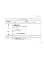
Page 16: ...The Meter reads PoFF until A is released B Any switch position Power up Starts recording of minimum and maximum values and disables power off feature Steps the display through MAX MIN AVG average and...

Page 17: ...toHOLD captures the present reading on the display When a new stable reading is detected the Meter beeps and displays the new reading Stops and starts recording without erasing recorded values Stops a...

Page 18: ...he present reading as a reference for subsequent readings The display is zeroed and the stored reading is subtracted from all subsequent readings Enables zoom mode for the bar graph The Meter reads 2r...

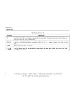
Page 19: ...his sign indicates that the present input is less than the stored reference F Z Indicates the presence of a high voltage input Appears if the input voltage is 30 V or greater ac or dc Also appears in...

Page 20: ...tically selects the range with the best resolution P Manual The Meter is in manual range mode Q The number of segments is relative to the full scale value of the selected range In normal operation 0 z...

Page 21: ...ly turns off if you do not turn the rotary switch or press a button for 30 minutes If MIN MAX Recording is enabled the Meter will not power off To disable automatic power off refer to Table 4 Input Al...

Page 22: ...ror is negligible 0 1 or less if the circuit impedance is 10 k 10 000 or less For better accuracy when measuring the dc offset of an ac voltage measure the ac voltage first Note the ac voltage range t...

Page 23: ...0 F to 1994 0 F the included K Type Thermocouple is rated to 260 C For temperatures out of that range use a higher rated thermocouple Display ranges are 200 0 C to 1090 0 C and 328 0 F to 1994 0 F Rea...

Page 24: ...ong as a circuit is complete The beeper allows you to perform quick continuity tests without having to watch the display To test for continuity set up the Meter as shown in Figure 3 Press Eto turn the...

Page 25: ...Hz AutoHOLD A mA COM 400mA FUSED 10A MAX FUSED A 88 MIN MAX RANGE REL Hz AutoHOLD A mA COM 400mA FUSED 10A MAX FUSED A 88 For in circuit tests turn circuit power off OFF open ON closed Activates cont...

Page 26: ...4 The following are some tips for measuring resistance The measured value of a resistor in a circuit is often different from the resistor s rated value The test leads can add 0 1 to 0 2 of error to re...

Page 27: ...MAX RANGE REL Hz AutoHOLD A mA COM 400mA FUSED 10A MAX FUSED A 88 Circuit Power OFF In Circuit Resistance Measurements 1 Disconnect Isolating a Resistor Disconnect 2 3 Isolating a Potentiometer 1 3 2...

Page 28: ...DIS coil packs on a car To measure conductance set up the Meter as shown for measuring resistance Figure 4 then press Cuntil the nS indicator appears on the display The following are some tips for mea...

Page 29: ...er s capacitance ranges are 10 00 nF 100 0 nF 1 000 F 10 00 F 100 0 F and 9999 F To measure capacitance set up the Meter as shown in Figure 5 To improve the accuracy of measurements less than 1000 nF...

Page 30: ...of a circuit set up the Meter as shown in Figure 6 For forward bias readings on any semiconductor component place the red test lead on the component s positive terminal and place the black lead on th...

Page 31: ...REL Hz AutoHOLD A mA COM 400mA FUSED 10A MAX FUSED A 88 MIN MAX RANGE REL Hz AutoHOLD A mA COM 400mA FUSED 10A MAX FUSED A 88 Typical Reading Forward Bias Reverse Bias Bad Diode Open Bad Diode Shorte...

Page 32: ...Meter in series with the circuit The Meter s current ranges are 600 0 A 6000 A 60 00 mA 400 0 mA 6000 mA and 10 A To measure current refer to Figure 7 and proceed as follows 1 Turn off power to the ci...

Page 33: ...iven at the right side of the display A mA or A 7 Turn off power to the circuit and discharge all high voltage capacitors Remove the Meter and restore the circuit to normal operation The following are...

Page 34: ...8 Circuit Power OFF to connect meter ON for measurement OFF to disconnect meter 4 3 Total current to circuit Current through one component 2 5 5 ayg07f eps Figure 7 Measuring Current Test Equipment De...

Page 35: ...99 9 Hz 19 999 kHz 199 99 kHz and greater than 200 kHz For frequencies below 10 Hz the display is updated at the frequency of the input Below 0 5 Hz the display may be unstable The following are some...

Page 36: ...mV 40 mV Refer to the measurement tips given on page 27 L 6 V 1 7 V 5 V logic signals TTL L 60 V 4 0 V Automotive switching signals L 600 V 40 V Refer to the measurement tips given before on page 27 L...

Page 37: ...e set up the Meter to measure frequency then press G a second time As with the frequency function you can change the slope for the Meter s counter by pressing E For 5 V logic signals use the 6 V dc ra...

Page 38: ...measured value and is relative to the full scale value of the selected range In the 60 V range for example the major divisions on the scale represent 0 15 30 45 and 60 V An input of 30 V lights the n...

Page 39: ...ess H again for one second MIN MAX Recording Mode The MIN MAX mode records minimum and maximum input values When the inputs go below the recorded minimum value or above the recorded maximum value the...

Page 40: ...e signal extremes lasting longer than 250 s Smooth Feature Power Up Option Only When the input signal changes rapidly smoothing provides a steadier reading on the display by averaging multiple samples...

Page 41: ...minimum or maximum value is recorded B while in MIN MAX mode Step through maximum MAX minimum MIN average AVG and present values E PEAK MIN MAX Select 100 ms or 250 s response time The 250 s response...

Page 42: ...uent measurements The Meter is locked into the range selected when you pressed F Press Fagain to exit this mode In relative mode the reading shown is always the difference between the present reading...

Page 43: ...in the spark plug wire and converts it to a pulse that triggers the Meter s RPM measurement The Meter can also read RPM directly from appropriate signals like the camshaft position sensor or tach sign...

Page 44: ...or systems that fire every revolution 2 cycle engines and for DIS waste spark systems press A twice to select RPMn 5 Clamp the Inductive Pickup to a plug wire near the spark plug Make sure that the ja...

Page 45: ...Multimeter Using the Meter for Automotive Applications MIN MAX RANGE REL Hz AutoHOLD A mA COM 400mA FUSED 10A MAX FUSED A 88 3 2 5 SPARK PLUG SIDE 6 4 ayg21f eps Figure 9 Measuring RPM with Inductive...

Page 46: ...pear at the right side of the display Use E to change trigger slope 5 With the ignition KEY ON but the ENGINE OFF KOEO pump the vacuum up 6 Watch the frequency change on the display Compare the freque...

Page 47: ...Multimeter Using the Meter for Automotive Applications MIN MAX RANGE REL Hz AutoHOLD A mA COM 400mA FUSED 10A MAX FUSED A 88 2 1 6 4 3 ayg22f eps Figure 10 Testing MAP or BP MAP Sensors with Frequency...

Page 48: ...in the input terminals shown in Figure 11 2 Turn rotary switch to N 3 Touch the probes as shown to measure resistance in primary windings 4 Observe display Resistance should be less than a few ohms 5...

Page 49: ...motive Applications 3 MIN MAX RANGE REL Hz AutoHOLD A mA COM 400mA FUSED 10A MAX FUSED A 88 MIN MAX RANGE REL Hz AutoHOLD A mA COM 400mA FUSED 10A MAX FUSED A 88 2 1 4 6 5 ayg11f eps Figure 11 Measuri...

Page 50: ...n next to Trig in the lower left corner of the display To measure pulse width on most port fuel injectors 1 Insert test leads in the input terminals shown in Figure 12 2 Set the rotary switch to L 3 C...

Page 51: ...ve Multimeter Using the Meter for Automotive Applications 3 MIN MAX RANGE REL Hz AutoHOLD A mA COM 400mA FUSED 10A MAX FUSED A 88 2 1 4 5 ayg12f eps Figure 12 Measuring Pulse Width on a Port Fuel Inje...

Page 52: ...ernator not at the battery 1 Insert the test leads as shown in Figure 13 2 Set the rotary switch to K 3 Touch the red probe to the BAT side of the alternator and the black probe to ground 4 Read the d...

Page 53: ...motive Multimeter Using the Meter for Automotive Applications MIN MAX RANGE REL Hz AutoHOLD A mA COM 400mA FUSED 10A MAX FUSED A 88 2 4 1 3 ayg16f eps Figure 13 Testing Ripple Voltage on an Alternator...

Page 54: ...rotary switch to L 3 Press C three times to select the 6 V range 4 Connect the test leads as shown 5 Start the engine If the oxygen sensor is unheated fast idle the car for a few minutes Then press B...

Page 55: ...e Multimeter Using the Meter for Automotive Applications MIN MAX RANGE REL Hz AutoHOLD A mA COM 400mA FUSED 10A MAX FUSED A 88 3 5 2 1 4 6 ayg14f eps Figure 14 Measuring Voltages on a Typical Oxygen S...

Page 56: ...Set the rotary switch to M If you are measuring over 600 mV 0L will appear Switch to L and select the 6 V range 3 Press D RS is displayed 4 Touch probes across the connection to be measured 5 Crank e...

Page 57: ...motive Multimeter Using the Meter for Automotive Applications MIN MAX RANGE REL Hz AutoHOLD A mA COM 400mA FUSED 10A MAX FUSED A 88 3 2 5 1 4 ayg17f eps Figure 15 Measuring Starter Circuit Voltage Dro...

Page 58: ...ull open and back to the throttle stop to test the full motion of the sensor Press B to read the minimum and maximum values Testing the Throttle Position Sensor Resistance 1 Insert test leads in the i...

Page 59: ...e Multimeter Using the Meter for Automotive Applications MIN MAX RANGE REL Hz AutoHOLD A mA COM 400mA FUSED 10A MAX FUSED A 88 7 1 5 4 3 ayg15f eps Figure 16 Testing the Throttle Position Sensor Resis...

Page 60: ...other while reading the display 5 Current reading will drop when the fuse on the bad circuit is pulled 6 Reinstall fuse and test components including connectors of that circuit to find defective compo...

Page 61: ...otive Multimeter Using the Meter for Automotive Applications MIN MAX RANGE REL Hz AutoHOLD A mA COM 400mA FUSED 10A MAX FUSED A 88 4 2 5 1 3 ayg18f eps Figure 17 Isolating Circuit Causing Current Drai...

Page 62: ...arge not the battery condition To measure system voltage 1 Insert test leads in the input terminals shown in Figure 18 2 Set the switch to V 3 Turn on lights for 1 minute to bleed off surface charge 4...

Page 63: ...otive Multimeter Using the Meter for Automotive Applications MIN MAX RANGE REL Hz AutoHOLD A mA COM 400mA FUSED 10A MAX FUSED A 88 2 5 4 1 ayg19f eps Figure 18 Measuring the No Load Voltage of a Batte...

Page 64: ...leads in the input terminals shown in Figure 19 2 Turn rotary switch to N 3 Press the E button 4 Connect probes to stoplight switch 5 Press brake pedal and listen for tone If tone sounds stoplight sw...

Page 65: ...Automotive Multimeter MIN MAX RANGE REL Hz AutoHOLD A mA COM 400mA FUSED 10A MAX FUSED A 88 2 3 5 4 5 1 ayg20f eps Figure 19 Testing for Continuity in a Switch 57...

Page 66: ...ly on the terminals Testing the Fuse If a test lead is plugged into the mA A or A terminal and the rotary switch is turned to a non current function the Meter chirps and flashes LEAd if the fuse assoc...

Page 67: ...or 006P XWWarning To avoid false readings which could lead to possible electric shock or personal injury replace the battery as soon as the battery indicator b appears If the display shows bAtt the M...

Page 68: ...lacement fuses with the amperage voltage and speed ratings shown in Table 10 7 Verify that the rotary switch and the circuit board switch are in the OFF position 8 Replace the case top ensuring that t...

Page 69: ...Automotive Multimeter Service and Parts F1 F2 ayg33f eps Figure 21 Battery and Fuse Replacement 661...

Page 70: ...ottom 1 2074025 MP5 Case Top PAD XFER with Window 88 V 1 2115202 MP6 Case Bottom 1 2073871 MP8 Knob Switch PAD XFER 1 2100482 MP9 Detent Knob 1 822643 MP13 Shock Absorber 1 828541 MP14 O Ring Input Re...

Page 71: ...er MP390 391 Access Door Fastener 2 948609 U5 LCD 4 5 DIGIT TN Transflective Bar Graph OSPR80 1 2065213 CR6 Light pipe 1 2074057 S2 Keypad 1 2105884 TM1 Model 88 V Automotive Multimeter Users Manual t...

Page 72: ...4 BT1 H5 6 MP5 MP6 Holster MP15 S2 MP22 MP11 MP10 W Tilt Stand MP2 U5 MP31 MP4 MP8 CR6 ayg34f eps Figure 22 Replaceable Parts Test Equipment Depot 800 517 8431 99 Washington Street Melrose MA 02176 F...

Page 73: ...ed AC285 Sure Grip Wide Jaw Alligator Clips AC89 Insulation Piercing Clip PV350 Pressure Vacuum Module RPM80 Inductive Clamp included TL224 Sure Grip Test Lead Set Heat Resistant Silicone included TL7...

Page 74: ...curacy C 18 C or 28 C Electromagnetic Compatibility All ranges unless otherwise noted In an RF field of 3 V m total accuracy specified accuracy 20 counts Except 600 UA dc range total accuracy specifie...

Page 75: ...reading number of least significant digits at 18 C to 28 C with relative humidity up to 90 for a period of one year after calibration AC conversions are ac coupled and are average responding rms indi...

Page 76: ...1 1 When using the REL function to compensate for offsets 2 Add 0 5 of reading when measuring above 30 M in the 50 M range and 20 counts below 33 nS in the 60 nS range Table 14 Temperature Specificati...

Page 77: ...A2 0 01 mA 0 1 mA 0 001 A 0 01 A 0 4 4 0 4 2 0 4 4 0 4 2 1 8 mV mA 1 8 mV mA 0 03 V A 0 03 V A A B 45 Hz to 2 kHz 600 0 A 6000 A 0 1 A 1 A 1 2 2 3 1 2 2 3 100 V A 100 V A AF 600 0 A 6000 A 0 1 A 1 A...

Page 78: ...0 00 nF 100 0 nF 1 000 F 10 00 F 100 0 F 9999 F 0 01 nF 0 1 nF 0 001 F 0 01 F 0 1 F 1 F 1 2 1 1 2 1 1 2 1 2 1 2 1 2 G 3 000 V 0 001 V 2 1 1 With a film capacitor or better using Relative mode to zero...

Page 79: ...1999 9 5 00 0 500 0 0500 0 1 0 01 0 001 0 0001 RPM n 30 to 9 0004 1 RPM 2 RPM RPM o 60 to 12 0004 1 RPM 2 RPM Duty Cycle3 0 0 to 99 9 0 5 Hz to 200 kHz Pulse Width 2 s Pulse Width3 0 002 to 1999 9 ms...

Page 80: ...C Voltage Function 600 mV dc 600 mV ac 6 V 60 V 600 V 1000 V 70 mV to 400 Hz 150 mV 0 3 V 3 V 30 V 100 V 70 mV to 400 Hz 150 mV 0 7 V 7 V 140 kHz 70 V 14 0 kHz 200 V 1 4 kHz 40 mV 1 7 V 4 V 40 V 100 V...

Page 81: ...20 dB at dc 50 Hz or 60 Hz 60 dB at 50 Hz or 60 Hz F mV 1000 V 10 M 100 pF 120 dB at dc 50 Hz or 60 Hz 60 dB at 50 Hz or 60 Hz K 1000 V 10 M 100 pF ac coupled 60 dB dc to 60 Hz Open Circuit Full Scale...

Page 82: ...ion 120 ms to 80 ac functions Specified accuracy 40 counts for changes 350 ms and inputs 25 of range 250 s peak 1 Specified accuracy 100 counts for changes 250 s in duration add 100 counts for reading...

Reviews: