background image

ECLIPSE

Installation and operating manual

Document release 3.1, 2/12/2016

For software version: CORE 7.12M

1

Summary of Contents for Eclipse

Page 1: ...ECLIPSE Installation and operating manual Document release 3 1 2 12 2016 For software version CORE 7 12M 1 ...

Page 2: ... 19 Video inputs 20 GPS 20 Altitude serial out for transponder connection 20 Separable connectors for thermocouples 21 PART II OPERATING MANUAL 5 1 Display cleaning 23 5 2 Panel indicators and commands 23 5 3 Using the menus 24 6 Instrument configuration 25 6 1 System setup menu 25 6 1 1 Sensor setup menu 25 6 1 2 Gauge setup menu 26 CHT gauge setup 26 EGT gauge setup 27 Oil temperature gauge setu...

Page 3: ...on 41 Fuel computer section 41 Fuel flow 42 Remaining fuel 42 Burned fuel 42 Endurance 42 Range 42 Reserve 42 8 2 PFD Section 43 Heading Tracking indicator 43 Turn rate 44 Air speed 44 Attitude indicator 44 G meter 44 Slip indicator 45 Vertical speed indicator 45 Altimeter 45 Status indicator 45 Ground speed 45 Wind speed direction 45 8 3 IFIS Section for ECLIPSE IFIS only 46 8 4 Video Cameras sec...

Page 4: ...his document must accompany the instrument in the event of change of ownership The pilot must understand the operation of this instrument prior to flight and must not allow anyone to use it without knowing the operation Don t use this instrument in flight until you are sure of the correct operating of the same When the installation is finished you must do a test prior to flight switching on all th...

Page 5: ...c calibration after the installation of your Eclipse is an essential procedure that you must perform before you fly Not only the heading but also the attitude indicator depends on a correct magnetic calibration Without it there is no data stored for the magnetic sensors and the attitude indicator that use this data also may not work correctly The magnetic calibration it s a simple procedure that i...

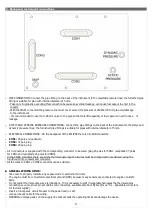
Page 6: ...ECLIPSE PART I INSTALLATION 6 ...

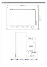
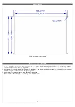
Page 7: ...2 Dimensions 7 ...

Page 8: ...er and lower part of the instruments leave as much space as possible During use the instrument become warm so it s necessary to have some air circulation inside the instruments room to avoid that the temperature increase over the operating limits Avoid placing n hot locations for example near heater vents Find a location where the display will always be completely visible 8 ...

Page 9: ...B connectors CON1 25 poles receptacle CON2 37 poli plug CON3 25 poli plug All 3 connectors is supplied with the corresponding connector to be wired plug 25 poles for CON1 receptacle 37 poles for CON2 and receptacle 25 poles for CON3 In the CON3 connector there are all the thermocouple inputs all wires must be crimped and not soldered using the furnished crimp contacts and connector All the wires t...

Page 10: ...l for connection with ACU see chap 10 3 3 10 positive microphone input currently not used 11 GND 12 Not used Reserved 13 Not used Reserved 14 Not used Reserved 15 Not used Reserved 16 5V for GPS connect to red wire of Flybox GPS 17 GPS TX connect to black wire of Flybox GPS 18 Altitude serial out for transponder 19 GND for altitude serial out connect to copper shield 20 CAN0 L signal for connectio...

Page 11: ... external GPS connection to pin 6 is used for RESERVE indication of Fuel Computer and for the NAV function if you have installed also the Flybox ACU autopilot control unit To enable the external GPS enter in the menu Fuel Computer and set the Ext GPS for reserve indication to YES 11 ...

Page 12: ...deo input 2 16 GND for video input 3 17 12V for camera 3 18 Open collector alarm out active low max 400mA 5W 19 RPM pickup input 20 GND for current sensor 21 12V for fuel flow sensor 22 Fuel flow sensor input 23 GND for fuel pressure sensor 24 12V for capacitive fuel level sensor if used 25 RIGHT Televel input 26 12V for capacitive fuel level sensor if used 27 Not used Reserved 28 Oil pressure sen...

Page 13: ...dy connected the high level audio output as explained in CON1 connections The low level output require more accurate wiring because is more susceptible to electric noise use shielded wire and keep away from source of electric noise like for example radio antenna or wirings For this reason is generally preferable to use the high level audio output and leave unused the low level output 13 ...

Page 14: ...le 10 EGT4 thermocouple 11 EGT5 thermocouple 12 EGT6 thermocouple 13 Not used 14 CHT1 sensor input Rotax KTY PT1000 or thermocouple 15 CHT2 sensor input Rotax KTY PT1000 or thermocouple 16 CHT3 sensor input Rotax KTY PT1000 or thermocouple 17 CHT4 sensor input Rotax KTY PT1000 or thermocouple 18 CHT5 sensor input Rotax KTY PT1000 or thermocouple 19 CHT6 sensor input Rotax KTY PT1000 or thermocoupl...

Page 15: ... CHT2 CHT3 CHT4 If you use all 6 inputs with 6 thermocouples the autopilot remote button can t be connected EGT sensors Up to 6 EGT K type thermocouples can be installed Thermocouple type sensors have a two wire connection positive wire and negative wire The positive wire is connected to pins 20 to 25 EGT1 to EGT6 of CON3 connector the negative wire is connected to pins 7 to 12 of CON3 connector N...

Page 16: ...otax 912 914 pickup and other similar types of tachometer transducer Connect the transducer output to pin 19 of CON2 connector Outside air temperature sensor OAT The supported types of OAT sensors are PT1000 resistive sensors Connect one wire to pin 11 of CON2 connector and the other wire to aircraft ground Flybox OAT sensor Flybox OAT sensor is a PT1000 and can be fixed with a 5 mm countersunk sc...

Page 17: ... it s possible to perform current sensor calibration in this way 1 Connect only the 3 wire from current sensor to the ECLIPSE and leave disconnected the 2 battery cable inputs that is A and A in figure above 2 Now it s required to turn on th ECLIPSE so temporarily connect together the two cable A and A 3 Turn on th ECLIPSE and read the numeric value for the current indicator if it s zero there is ...

Page 18: ...eakage and aging To inspect and clean the sensor open it remove the sensor tube from the fuel system and look inside the two fittings to check for material integrity aging and deformation In case of any anomaly of the sensor tube it must be replaced Verify that the sensor tube is clean and without any obstruction If necessary clean with a flow of fuel in the opposite direction The fuel flow transd...

Page 19: ...ECLIPSE will display inaccurate readings For example pic 1 if a fuel sensor cannot measure the lowest part of the tank that contains 7 liters ECLIPSE will display 0 zero for fuel level of 7 liters and below Another example pic 2 is if a tank can holds 40 liters of fuel but at 25 liters the fuel is at the top of the sensor the maximum that ECLIPSE will display is 25 liters PIC 1 PIC 2 Fuel pressure...

Page 20: ...shielded cable connect it to CON1 ECLIPSE connector as follows RED WIRE to pin 16 BLACK WIRE to pin 17 COPPER SHIELD to pin 5 Altitude serial out for transponder connection If you use a transponder with serial input for receiving the altitude data it can be connected to the Eclipse by following this steps Ensure there is a shared ground between the Eclipse and the transponder Wire a serial transmi...

Page 21: ...s CONNECT TO PIN OF CON3 CONNECTOR THERMOCOUPLES NOTE Wires color are referred to Flybox supplied thermocouples other thermocouples may have different colors coding In case of wrong wiring the temperature indication will not be correct 21 ...

Page 22: ...ECLIPSE PART II OPERATING MANUAL 22 ...

Page 23: ...isplay use the supplied smooth cloth slightly moistened with alcohol Do not use other cleaners that may damage the display anti reflective coating 5 2 Panel indicators and commands ECLIPSE have 4 buttons that in this manual are indicated with the labels P1 P2 P3 P4 and a knob with pushbutton 23 ...

Page 24: ... to the knob rotate it until the function become selected and then press the knob To clarify the operating mode of the menus we explain below an example of operation In this example P1 button is assigned to EIS function P2 button to ZERO PITCH function P3 button to TRK function Rotating the knob will select one of the available functions LOG MARK CAMERAS ALT BUG HDG BUG AP DIMMER RESET G pressing ...

Page 25: ...ine and fuel management data version ECLIPSE MFD Multi Function Display copilot side version that permits viewing all data available from main ECLIPSE unit EIS PFD or IFIS Note also that functions and screens of your ECLIPSE may differ from what depicted in this manual depending on what optional sensors you had installed 6 1 System setup menu Press both P1 and P4 buttons for 2 seconds to enter in ...

Page 26: ...talled P1K PT1000 resistive sensor NO no OAT sensor installed NOTE If you use original Flybox OAT sensors select P1K type FP sensor YES NO Select whether you installed or not the Flybox fuel pressure sensor AMP sensor YES NO Select whether you installed or not the Flybox current sensor AMP offset Calibration of battery current sensor See Current sensor in chap 4 6 1 2 Gauge setup menu In gauge set...

Page 27: ...ax set the top limit of the oil temperature gauge High set the transition temperature from high yellow to red zone of the oil temperature gauge Mid set the transition temperature from green to high yellow zone of the oil temperature gauge Low set the transition temperature from low yellow to green zone of the oil temperature gauge Min set the bottom limit of the oil temperature gauge Clearance set...

Page 28: ...ssure from green to red zone of the CAT gauge Min set the bottom limit of the CAT gauge OAT GAUGE SETUP Max set the top limit of the OAT gauge Min set the bottom limit of the OAT gauge RPM GAUGE SETUP Max set the top limit of the RPM gauge High set the transition RPM from yellow to red zone of the RPM gauge Mid set the transition RPM from green to yellow zone of the RPM gauge Low set the bottom li...

Page 29: ...the bottom limit of the voltage gauge AMP GAUGE SETUP Max set the top limit of the current meter gauge Low set the transition voltage from yellow to green zone of the current meter gauge Min set the bottom limit of the current meter gauge ASI GAUGE SETUP NOTE The default speed are all set to zero Its mandatory to check your aircraft characteristics speed and set the following parameters accordingl...

Page 30: ... alarm every time the quantity of fuel used equals this value showing TANK BALANCE on the display To disable this function set the value to zero Tank capacity Set the tank capacity if there are more than one tank set the total capacity of the tanks K factor Set the fuel flow transducer s K factor K factor of a fuel flow transducer is the number of electric pulses for 1 gallon of fuel consumption K...

Page 31: ...el RES for resistive fuel sensors that decrease resistance as you add fuel If you don t know what type of resistive sensors are installed please see chapter 7 3 1 Fuel level sensors checkings CAP for capacitive fuel sensors DRES for fuel sensors model DRES Right tank sensor Set the fuel level sensor type installed in the RIGHT tank Main tank sensor Set the fuel level sensor type installed in the M...

Page 32: ...ns that the readings will be more slow and stable Usually there is no need to change this parameters because the default value are mostly correct 6 1 6 Video setup menu The video setup permits to correct brightness contrast and saturation for every of the 3 video inputs available The submenu is identical for all the 3 video inputs CAM1 CAM2 and CAM3 Adjust Brightness Contrast and Saturation the vi...

Page 33: ... Activation delay number of seconds for which the measure must be over the threshold before the alarm is activated Below are explained the additional parameters present in some submenus CHT and EGT ALARM SETUP Low threshold if you prefer an alarm even when the temperatures drop below the minimum thresholds select LOW MID or MIDLOW The values which refers are the same set in the Gauge Setup menu se...

Page 34: ... due to installation Rotate slowly the knob until the number at the right become zero then press it to store this value Turn off and on the instrument after storing a new inclination value RPM flight timer start threshold set the RPM required to start the flight timer the flight timer start automatically when the engine s RPM meets or exceeds this parameter for 30 seconds RPM counter multiplier ra...

Page 35: ... are available newer firmware versions ECLIPSE show a screen like the following notice the START UPGRADE indication To proceed with the upgrading procedure press YES P3 button ECLIPSE will show a screen with the current upgrading status Wait until all availables firmware is upgraded completely When the procedure is completed ECLIPSE will show the following screen Now your ECLIPSE is correctly upgr...

Page 36: ...tic fields metallic shed concrete floors with metal armatures etc and where is possible to execute more turn with the aircraft on the ground Turn on all the electric load usually used in flight On the ECLIPSE enter in the setup menu go in Password and insert the password 2 4 0 0 Press the START button Wait the indication MAKE A 420 DEGREE CLOCKWISE CIRCLE SLOWLY on the display then start with the ...

Page 37: ...rning on the ECLIPSE 4 Fill the tank s with the exact same level reached in the step 1 accurately measuring the quantity of fuel added in the tank s 5 Turn on the ECLIPSE select NO REFUEL even if you have refilled is required to select NO REFUEL 6 Select the K factor auto calibration menu System setup Fuel computer and press the knob for 3 seconds until it s displayed the following screen Rotate t...

Page 38: ...ibration choose the tank to calibrate and select the relative item in the setup menu System setup Fuel level Tanks setup Left Right Main tank calibration The display shows this screen in the example that follow the unit of measure are set to liters the Calib step is set to 5 and the tank choosed for calibration is the LEFT This screen is a calibration summary table every calibration steps is repre...

Page 39: ...f one of this conditions occur during calibration the ECLIPSE notice that the fuel sensor doesn t produce an electrical change and ask the user if fuel was already added for that calibration step If you are sure to have already added the fuel click on YES otherwise click on NO to go back to previous calibration step 7 3 1 Fuel level sensors checkings To operate correctly the fuel level indicators ...

Page 40: ... both graphical and numerical indication The numeric indicator is normally white but become yellow or red when enter in this ranges MAP with both graphical and numerical indication in inches of mercury Oil pressure with both graphical and numerical indication in BAR Oil temperature with both graphical and numerical indication in C EGT and CHT with graphical indications complete cylinders indicatio...

Page 41: ...n all the measures becomes in its green zone ECLIPSE will show the word READY that disappear 30 seconds after take off and is replaced by the flight timer indicated with FT FUEL LEVELS SECTION The fuel level indications are obtained by reading the fuel level sensors installed in your aircraft and connected to ECLIPSE The indications are approximated do not solely rely on the ECLIPSE to determine t...

Page 42: ... of measure the flow is indicated in liters Lt or gallons Gl NOTE The fuel remaining displayed here is not a measurement of the fuel in the tank but it is calculated from the initial quantity and the burned quantity measured from the fuel flow transducer BURNED FUEL Display the fuel burned from the starting According to the selected unit of measure the flow is indicated in liters Lt or gallons Gl ...

Page 43: ...wn as N S W E It can show the HEADING magnetic compass indicated with HDG or the TRACKING Track of the GPS indicated with TRK Note that after power on the compass is set to heading and is switched to tracking when speed exceeds 60 Km h It s however possible to switch between the two indications press any buttons to display the menu then press P3 button Heading and tracking considerations The Headi...

Page 44: ...he horizon line major pitch marks and numeric indicators are shown for every 10 up to 40 Minor pitch marks are shown for every 5 The roll scale show inclinations from 60 to 60 mark lines are shown for the following inclination The colors used for the attitude indicator are brown for the ground and sky blue for the sky The zero is represented by the red line IMPORTANT NOTES ON USING attitude indica...

Page 45: ...GROUND SPEED The ground speed is read from the GPS the unit of measure is the same of the air speed indicator If the GPS is not connected it will show the NO GPS indication if the GPS don t have the fix it will show NO FIX WIND SPEED DIRECTION Wind speed WS is indicated with the same unit of measure of the air speed Wind direction WD is represented graphically by an arrow and is also indicated in ...

Page 46: ...ame explained in the EIS section FUNCTIONS MENU AVAILABLE press any key to display the menu PFD to switch to PFD page ZERO PITCH Reset the pitch of the attitude indicator This function must be used only when the aircraft is in leveled flight never use it to reset the horizon during other flight attitude TRK or HDG to switch between Heading Tracking compass indications ENGINE or FUEL TIMER to switc...

Page 47: ...nput 3 SYSTEM SETUP Press P1 P4 for 2 seconds In the single video input fullscreen visualization select BACK button to return in the preview page or select ZOOM CAM to switch directly from one to another video input 8 5 Datalogger The datalogger is a useful data recording tool that permits later viewing in both graphical or numerical representation It also allow the download of the data in a SD ca...

Page 48: ...ation All numerical values are relative to the actual position of the cursor rotate the knob to move the cursor The Mark is a graphical reference that can be used during the flight to store a particular moment that can be easily find out on the graphic it will be stored also on the KML file for Google Earth To store a new mark during a flight select the Log Mark item from the menu bar Graphics are...

Page 49: ...ick on the KML file to view the recorded flight FLYDLxxx CSV xxx ID number of the flight generic comma separated value file format importable by any spreadsheet software like Excel Inside this CSV there are all the parameters recorded by ECLIPSE that is all engine data for ECLIPSE EIS all flight data for ECLIPSE PFD and both engine and flight data for ECLIPSE IFIS For example if you save to SD the...

Page 50: ...r section TANK SWITCHING Alert switching tank for balancing calculated by the fuel computer section WARNING OVER G WARNING OVERSPEED CAUTION LOW BATTERY VOLTAGE CAUTION LOW FUEL PRESSURE CAUTION LOW OIL PRESSURE CAUTION ENGINE OVERSPEED CAUTION MAXIMUM NO OXYGEN ALTITUDE HIGH OIL TEMPERATURE LOW OIL TEMPERATURE 8 7 Error messages Similar to the alarm conditions of the previous chapter various erro...

Page 51: ...rsion has the same design of the other 3 ECLIPSE models but it does not have any sensors integrated it shows all data available on the main ECLIPSE to which is connected INSTALLATION AND DIMENSIONS same as EIS PFD IFIS ECLIPSE refer to chapter 2 ELECTRICAL WIRING Unlike the main ECLIPSE unit in the MFD there is only the CON1 connector 51 ...

Page 52: ...onnection with main ECLIPSE unit connect to pin 7 of main ECLIPSE 8 Not used 9 Not used 10 Not used 11 Not used 12 Not used 13 Not used 14 12V for optional auxiliary backup battery 15 Not used 16 Not used 17 Not used 18 Not used 19 Not used 20 CAN0L signal for connection with main ECLIPSE unit connect to pin 20 of main ECLIPSE 21 Not used 22 Not used 23 Not used 24 Not used 25 Not used NOTE Use tw...

Page 53: ...PSE MFD is unable to communicate with the main unit for example if the main unit is not connected or turned off it display the following screen As soon as communication is established between the two instruments it become available the same pages available in the main ECLIPSE If the main unit is ECLIPSE IFIS all 3 pages are available see IFIS PFD EIS sections If the main unit is ECLIPSE PFD only P...

Page 54: ...l Unit ACU 3 Electrical installation wirings between Eclipse ACU and between ACU servos 4 Ground based test and configuration of the autopilot system 5 Flight based test and calibration of the autopilot system 10 3 1 Mechanical installation of the servo s The Flybox FX75 digital servos incorporates important safety features It has a reliable disengaging system situations like severe turbolence or ...

Page 55: ...nical installation of the autopilot control unit Flybox ACU The ACU control unit is suited for ECLIPSE instruments so it has the same vertical dimension for easily installing it on the left or right of the ECLIPSE unit It s however possible to install the ACU horizontally contact Flybox to request the horizontal adhesive front panel Panel cutout required 120 x 36 1 mm Outer dimensions 139 1 x 42 1...

Page 56: ...s Autopilot If you have one servo only use a 4 Ampere breaker if you have two servos use a 7 5 Ampere breaker Wirings between ACU control unit and ECLIPSE the ACU is connected to the Eclipse with a two wires CAN bus communication line Use a two pole twisted cable or a two pole with shield cable shield connected to ground in one point only AWG24 wires should be enough Wirings of the servos each ser...

Page 57: ...itch Servo 6 Not used 7 12V for Roll Servo 8 Not used CONNECTIONS DETAIL FOR FX75 SERVO CONNECTOR Pin Description 1 12V power supply 2 Not used 3 Not used 4 CAN bus communication line CAN L signal 5 CAN bus termination 6 GND power supply 7 Not used 8 Not used 9 CAN bus communication line CAN H signal 10 CAN bus termination NOTE The CAN bus termination pin 5 connected with pin 10 must be done only ...

Page 58: ... CHECKS INDICATED BELOW HAVE BEEN PROPERLY COMPLETED AND CORRECT FUNCTIONS HAVE BEEN OBSERVED Verify that no controls are bindings during any position of the flight controls Verify that the servos when not engaged will not restrict movement of any flight controls including maximum limits of the flight controls 58 ...

Page 59: ...o activate the Control Wheel Steering CWS mode it s possible to fly the aircraft to a new heading traking or altitude and then release the button to let the autopilot acquire and mantain the new values 10 5 Autopilot system configuration After the physical installation of the autopilot system it s required to check the connections and configure the parameters as explained in the following two chap...

Page 60: ...complete procedure will be as follows Step 1 center the control stick in neutral position and then click on P3 button NEXT to go to the next step Step 2 position the control stick to the left limit without forcing paying attention to not move it in the pitch axis during the motion After doing so the calibration automatically switch to the next step Step 3 center the control stick in neutral positi...

Page 61: ...de and check that the flight control move as to decrease the aircraft altitude If movement direction of one or both servos is reversed it means that the calibration is wrong so NEVER ENGAGE THE AUTOPILOT IN FLIGHT but repeat the servos calibration procedure and check again 10 5 1 Communications check ground based Turn on Eclipse instrument only Turn on ACU control unit and check that appear AP OFF...

Page 62: ...ters to an airspeed hold mode to restore and maintain approximately the maximum airspeed The choice of the Max speed value must be made according to the characteristics of your aircraft it should be below the Vne speed of your aircraft but above the normal cruise speed to set Vne see chap 6 1 2 ASI GAUGE SETUP Max speed parameter cannot be set to a value above 95 of Vne so you should first check t...

Page 63: ...that the autopilot may slightly exceed from target value during regulation VS descent rate parameter setting ground based VS descent rate This parameter sets the average vertical speed for autopilot commanded descents The unit of measure is meters second or feet minute depending on what you have choosen for the altimeter The range min max is 50 2000 feet minute 0 1 10 meters second When selecting ...

Page 64: ...ode or press the NAV button if autopilot is in navigation mode Remember these actions so that it can be carried out instinctively in case of difficulties or emergencies Before starting the first test flight verify once more for safety that all the parameters are correctly set Enter in the System seyup by pressing P1 P4 buttons Rotate the knob to select the Autopilot menu and press it to enter Rota...

Page 65: ...hase you observe the autopilot behavior during a turn further optimizing the Gain parameter which as said is what establishes the autopilot response With the autopilot engaged in HDG TRK mode start an autopilot commanded turn by rotating the HDG TRK knob on the ACU control unit Repeat again some heading tracking change observing the behavior of the autopilot If the autopilot will cause excessive o...

Page 66: ...e To change the Gain parameter Enter in the System setup by pressing P1 P4 buttons Rotate the knob to select the Autopilot menu and press it to enter Rotate the knob to select the Pitch servo setup menu and press it to enter Rotate the knob to select the Gain parameter and press it Rotate the knob to change the value and press it to store the new value Altitude change During this phase you observe...

Page 67: ...n ACU and servos The airspeed measured is out of the minimum maximum range Min speed and max speed parameters 67 Heading tracking bug with autopilot engaged is in MAGENTA without autopilot is in YELLOW Autopilot status AP OFF when autopilot is not engaged AP HDG when autopilot is engaged and follow holds the magnetic heading AP TRK when autopilot is engaged and follow holds the GPS tracking AP NAV...

Page 68: ...ude indicator screen press any button to show up the menu bar rotate the knob to select the HDG BUG AP or ALT BUG AP item and press to select it after which press P2 button DISENGAGE AP Pressing the remote button if installed Turning off the ACU with the ON OFF switch Opening the circuit breaker which provides power to the ACU The ACU control unit must be turned off during landing and takeoff 10 8...

Page 69: ...hat the GPS input of the Eclipse is enabled enter in system setup by pressing P1 P4 buttons select the Fuel computer menu and check that the Ext GPS for reserve indication is set to YES Once in flight and with Eclipse already turned on turn on the ACU control unit via the ON OFF switch Set a flight plane or a GOTO in the external GPS Press the NAV button on the ACU control unit led will turn on No...

Page 70: ...imum limit see chap 10 6 3 for setting the pitch limit AUTOPILOT DISENGAGED AIRSPEED LIMIT Appears if you try to engage the autopilot when the airspeed is outside the minimum or maximum limits see chap 10 6 1 for setting the limits AUTOPILOT DISENGAGED ROLL or PITCH SERVO CALIB Appears if you try to engage the autopilot before completing the servos calibration procedure AUTOPILOT DISENGAGED ROLL o...

Page 71: ... ROTAX or JABIRU sensors Oil temperature from ROTAX JABIRU or resistive sensors Carburetor air temperature from resistive sensor Outside air temperature from resistive sensor 6 Cylinder head temperature from ROTAX J K thermocouples or resistive sensors 6 Exhaust gas temperature from J K thermocouples 3 inputs for fuel level sensors resistive or capacitive PFD MODEL SECTION All inertial and pressur...

Page 72: ... corrections 2 2014 2 8 CON1 connections 3 2014 2 9 Updated chap 8 5 5 2016 3 0 Updated autopilot with FX75 digital servomotors 12 2016 3 1 Updated fuel level tanks setup with backup restore options WARNING All photos data drawings instruments layouts technical solutions and data representation you find in this document or watching at Flybox instruments working and or you can access by means of an...

Reviews: