Flybox Oblo backup system 2.0, Manual
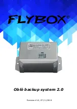
Introducing Flybox Oblo backup system 2.0 - an advanced and reliable data backup solution. Seamlessly protect your precious files with this cutting-edge product. For detailed instructions and step-by-step guidelines on setting up and using this backup system, download the comprehensive manual, available for free at 88.208.23.73:8080. Safeguard your data today!
Share
Download

Reviews:
No comments