background image

Installation, Operation and Service Manual 

00124438R02

C/E12CI400A

countertop dispenser

C/E12CI400A 

countertop dispenser with 

SensorSAFE

  actuation 

(shown with legs accessory)

C/E12HI400A

wall mount dispenser (available 

with or without drain pan)

Following installation, please forward this manual 

to the appropriate operations person.

801 Church Lane • PO Box D, Easton, PA 18044, USA
(610) 252-7301 • Fax (610) 250-0696 • www.follettice.com

12 Series - 220V 60Hz/230V 50Hz 

Ice and Water Dispensers 

Order parts online
www.follettice.com

Summary of Contents for C/E12CI400A

Page 1: ... legs accessory C E12HI400A wall mount dispenser available with or without drain pan Following installation please forward this manual to the appropriate operations person 801 Church Lane PO Box D Easton PA 18044 USA 610 252 7301 Fax 610 250 0696 www follettice com 12 Series 220V 60Hz 230V 50Hz Ice and Water Dispensers Order parts online www follettice com ...

Page 2: ... Follett and deemed suitable to be returned to stock Note A 15 restocking charge will be deducted from the credit If the cost to return the product to stock exceeds 15 the actual cost will be deducted Welcome to Follett Corporation Important cautions Specifications Installation Installing countertop dispensers without legs Installing countertop dispenser with legs accessory Installing wall mount d...

Page 3: ...CI400A Condenser type A air cooled Icemaker capacity in lbs per day Icemaker location I integral Dispenser configuration C countertop H wall mount Approximate storage capacity in lbs Alternate voltage C 220V 60Hz E 230V 50Hz Welcome to Follett Follett equipment enjoys a well deserved reputation for excellent performance long term reliability and outstanding after the sale support To ensure that th...

Page 4: ...hut off recommended within 3m 10 ft of dispenser Drain to be hard piped and insulated Maintain at least 20mm per 1m run 1 4 per foot of slope Ventilation clearances 6 153mm on right side of dispenser 6 153mm at top for ventilation and 12 305mm at top recommended for service Note Do not block right side air intake or top air exhaust Dry weight 79 4kg 175 lbs DRAIN ICE MACHINE MAKE UP WATER Dispense...

Page 5: ...nstallations where utilities exit through back of dispenser refer to back view drawings Wall mount models without drain pan are designed for use above sinks Counter depth must allow front of sink to be a minimum of 23 5 597mm from wall Installation procedures 1 Position dispenser in desired location mark dispenser outline on counter and remove dispenser 2 Regardless of whether utilities will exit ...

Page 6: ...talling countertop dispensers with legs accessory 1 Carefully tip dispenser back to expose underside and block up in place Note Do NOT tilt unit farther than 30 off vertical plane 2 Screw legs shipped taped to drain pan of dispenser into dispenser bottom taking care to seat legs securely against underside of dispenser Note Countertop dispensers that sit on legs not bolted to counter can be inadver...

Page 7: ...s shown Fig 10 2 Mount support bracket to wall using fasteners of sufficient strength fasteners not included see Fig 6 3 Rough in water and drain lines Fig 10 4 Lift dispenser onto support bracket positioning unit so that hook on back of dispenser is captured by support bracket angle Fig 7 5 Install two 2 supplied 3 8 16NC screws through bottom of support bracket into bottom of dispenser Fig 5 6 M...

Page 8: ...mm 3 outline of dispenser bottom of dispenser Fig 6 Wall mounting dimensions Caution Do NOT rest dispenser weight on bottom of support bracket Fig 7 Wall mount side view 572mm 22 5 826mm 32 5 470mm 18 5 Installing wall mount dispensers 493mm 19 375 597mm 23 5 minimum distance to sink front 8 ...

Page 9: ...own water and drain tubing 3 77mm 89mm 77mm 3 32mm 1 25 MAX 3 3 5 3 MIN 23mm 0 88 MIN 407mm 16 254mm 10 77mm 77mm wall nut support bracket screw bottom panel 19mm 3 4 FPT drain 10mm 3 8 push in water inlet Fig 8 Wall mount unit bottom panel assembly Fig 9 Wall mount bottom view Fig 10 Front view of wall mount bracket utility location Side view of utilities exiting wall ...

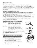
Page 10: ...lected infrared light to detect the presence of the container and send a signal to a control board which then activates the appropriate components for ice or water dispensing The SensorSAFE package includes a cleaning switch under the left side of the front cover which temporarily shuts off dispensing to allow cleaning of the panel and lenses If the switch is not turned back on after cleaning the ...

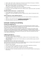
Page 11: ...frequently as recommended below and more often if environmental conditions dictate Cleaning of the condenser can usually be performed by facility personnel Cleaning of the icemaker system in most cases should be performed by your facility s maintenance staff or a Follett authorized service agent Regardless of who performs the cleaning it is the operator s responsibility to see that this cleaning i...

Page 12: ...lace a large pan in bin storage area to catch ice or connect a separate ice transport tube to evaporator and divert ice into separate container 15 Fill reservoir almost to overflowing with sanitizing solution 16 Restore power to icemaker gearmotor will run compressor and fan will not 17 After 10 minutes turn compressor switch to ON position 18 As unit starts to make ice continue to pour sanitizing...

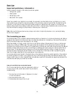
Page 13: ...ator and operates on a continuous freezing cycle Water is supplied to the evaporator from the water reservoir where the water level is controlled by a float valve This valve also shuts off the water supply when the icemaker is not running When the icemaker is running a layer of ice forms on the interior surface of the evaporator This ice is continuously removed by a rotating 12 RPM auger The auger...

Page 14: ...SE SWITCH WATER DISPENSE SWITCH WHITE 16 FAN START RELAY RUN START MOUNTED ON MAIN FRAME YELLOW BLACK GEAR MOTOR BLUE ORANGE 18 ORANGE 19 WHITE 15 BLACK 13 WHEEL 4 GREEN 27 BLACK 8 1 BLACK 9 WHITE 26 BLACK 10 SAFETY SWITCH HIGH PRESSURE RED 17 BLACK 38 WHITE 39 MAIN FRAME GRN TO POWER SWITCH ELEC BOX GRN IN WATER SENSOR COMPRESSOR BIN THERMO STAT 1 HIGH PRESSURE SAFETY SWITCH OPEN 425psi CLOSES 29...

Page 15: ...cuit is completed through the normally closed contacts of the bin thermostat and the bin signal switch When ice builds up around the bin thermostat the contacts open cutting the bin signal WHITE COMPRESSOR COMP START RELAY START RUN COMP START CAPACITOR Black R S C MAIN FRAME INTERNAL MOUNTED ON COMPONENTS OVER LOAD COMPRESSOR WHITE 16 FAN START RELAY RUN START MOUNTED ON MAIN FRAME YELLOW BLACK G...

Page 16: ...E BLACK FAN M ORANGE BLACK L N HIGH PRESSURE SAFETY SWITCH COMPRESSOR SWITCH DISPENSER Circuitry notes Compressor switch should read closed in ON position Bin signal is 16V DC Flashing water LED at any time indicates that water signal to board has been lost for more than one second Ten second delay There is a 10 second delay in reaction to loss of water WTR or bin B E signals If signals are not lo...

Page 17: ...NGE RED RED BLUE BLACK FAN M ORANGE BLACK L N HIGH PRESSURE SAFETY SWITCH COMPRESSOR SWITCH DISPENSER RED WTR B E B T 2ND 60M 20M C POWER DR WHITE BLACK YELLOW WHITE 4 3 2 T O L START RUN GEARMOTOR COMPRESSOR R POTENTIAL START RELAY RUN CAP CAPACITOR START C S 2 1 5 T O L L1 L2 COMP FAN DRV BIN T STAT BIN SIGNAL SWITCH WATER SENSOR G GREEN YELLOW GRND IN ELEC BOX BROWN BLUE WHITE WHITE BLACK BLACK...

Page 18: ...OWER DR WHITE BLACK YELLOW WHITE 4 3 2 T O L START RUN GEARMOTOR COMPRESSOR R POTENTIAL START RELAY RUN CAP CAPACITOR START C S 2 1 5 T O L L1 L2 COMP FAN DRV BIN T STAT BIN SIGNAL SWITCH WATER SENSOR G GREEN YELLOW GRND IN ELEC BOX BROWN BLUE WHITE WHITE BLACK BLACK ORANGE RED BLACK BLACK BLACK BLACK VIOLET VIOLET ORANGE ORANGE RED RED BLUE BLACK FAN M ORANGE BLACK L N HIGH PRESSURE SAFETY SWITCH...

Page 19: ... BLUE WHITE WHITE BLACK BLACK ORANGE RED BLACK BLACK BLACK BLACK VIOLET VIOLET ORANGE ORANGE RED RED BLUE BLACK FAN M ORANGE BLACK L N HIGH PRESSURE SAFETY SWITCH COMPRESSOR SWITCH DISPENSER RED WTR B E B T 2ND 60M 20M C POWER DR WHITE BLACK YELLOW WHITE 4 3 2 T O L START RUN GEARMOTOR COMPRESSOR R POTENTIAL START RELAY RUN CAP CAPACITOR START C S 2 1 5 T O L L1 L2 COMP FAN DRV BIN T STAT BIN SIGN...

Page 20: ... BLACK BLACK BLACK BLACK VIOLET VIOLET ORANGE ORANGE RED RED BLUE BLACK FAN M ORANGE BLACK L N HIGH PRESSURE SAFETY SWITCH COMPRESSOR SWITCH DISPENSER RED WTR B E B T 2ND 60M 20M C POWER DR WHITE BLACK YELLOW WHITE 4 3 2 T O L START RUN GEARMOTOR COMPRESSOR R POTENTIAL START RELAY RUN CAP CAPACITOR START C S 2 1 5 T O L L1 L2 COMP FAN DRV BIN T STAT BIN SIGNAL SWITCH WATER SENSOR G GREEN YELLOW GR...

Page 21: ...f the water level in the float reservoir drops to an unacceptable level the WTR LED goes out shutting the icemaker off Also the BT LED comes on preventing the icemaker from restarting for twenty minutes If water is restored the WTR LED comes back on and flashes to alert the technician that water to icemaker has been lost The icemaker restarts at the end of the 20 minute time delay The flashing WTR...

Page 22: ...ooled Ambient air temp 15 6 C 60 F 21 1 C 70 F 26 7 C 80 F 32 2 C 90 F 37 8 C 100 F 3 2A 3 3A 3 4A 3 5A 3 6A Locked rotor amps 26 3 Table 3 Gearmotor data Gearmotor current 1 3A nominal Locked rotor amps 6 8 amps Ambient air temperature C Icemaker inlet water temperature C C 10 21 32 16 12 1 6 12 1 6 13 1 1 7 27 16 9 2 1 16 8 2 1 18 3 2 2 38 16 3 2 5 22 5 2 6 23 9 2 8 bar bar bar Ambient air tempe...

Page 23: ...eached close valves and both manifold and shut down the vacuum pump Allow the system to sit for approximately 20 minutes During this period the system pressure should not rise If the system pressure rises and stabilizes there is moisture in the system and further evacuation is needed If the pressure continues to rise check the system for leaks Ambients Minimum Maximum Air temperature1 10 C 50 F 37...

Page 24: ...otor and capacitor and replace as required 4 Secure cover 1 Replace dispense switch 1 Check for proper positing if stat does not open when ice is places on capillary tube replace stat 1 Replace water solenoid valve 2 Replace dispense switch 3 Check switch turn on or replace if faulty Troubleshooting the dispenser lever models Ice capacity test Icemaker production capacity can only be determined by...

Page 25: ...ard Problem Dispenses ice and or water continuously Board guide LEDs when illuminated indicate the following PWR board power CLN cleaning no dispensing cycle ICE ice dispensing activated WTR water dispensing activated Terminals LI incoming power hot L2 neutral terminals WTR power terminal for water solenoid WM power terminal for wheelmotor CLN terminals for clean cycle switch Note SOL terminal not...

Page 26: ... 7 Superheat incorrect 8 Inefficient compressor 1 O ring seal broken Corrective action 1 Check that unit is plugged in circuit breakers are on 2 Adjust or replace ice level control 3 Check reservoir for water restore water to unit 4 See 6 below 5 Repair or replace gear motor 6 Replace gearmotor start relay 1 Clean condenser coil and replace overload if necessary 2 Replace start capacitor 3 Replace...

Page 27: ...hness or binding and replace if necessary 5 Replace gearmotor start relay 6 Ensure that ice contacts bin thermostat before backing ice up in transport tube Refer to dispenser manual for proper thermostat and ice tube mounting 1 Check for broken gearmotor output shaft or damaged gearbox 2 Check for defective water sensor water OK WTR LED remains on even when float empty or probe removed from water ...

Page 28: ...equence Wheelmotor removal 1 Remove dispense wheel and drive bar see above 2 Remove four 4 hopper support plate mounting screws and washers Fig 11 1 3 Move hopper assembly 1 2 13mm to left 4 Remove four 4 dispenser motor bracket mounting screws and washers Fig 11 2 5 Short shaft motors only loosen only two 2 lower screws on drive coupling and remove from motor shaft Fig 11 3 6 Remove four 4 screws...

Page 29: ...m evaporator port Evaporator reassembly 1 Clean gearmotor boss output shaft and shaft well 2 Install drain pan and evaporator mounting base 3 Fill gear motor shaft well with food grade grease 4 Install condensate shield and seat against gear motor boss 5 Install bearing O ring in groove in evaporator mounting base 6 Lower bottom bearing assembly into evaporator mounting base 7 While maintaining a ...

Page 30: ...nit and pull fan assembly toward front of unit c As fan assembly is being pulled toward front rotate assembly clockwise as shown above Fan removal Side panels Remove screw located on lower rear side Pull side panel toward front of unit and out of back panel Note Before removing right hand side remove side louver panel by lifting up and pulling forward on panel Front cover Remove 2 screws Lift cove...

Page 31: ... Ice transport tube tube may extend a maximum of 7mm 1 4 into ice bin Top View 25 ice tube gasket ice tube retainer 13mm 50 TYP 77mm 3 capillary tube bracket Ice transport tube replacement 1 Push tube onto evaporator port 2 Position clamp behind lip on evaporator port and tighten clamp 51mm 2 ...

Page 32: ... 102mm 4 adjustable set of 4 8 502924 Union bulkhead 10mm 3 8 9 502397 Lid top panel plastic 10 502396 Panel right side 11 502395 Panel left side 12 502422 Drain tube assembly wall mount w drain pan 13 502391 Drain tube assembly countertop 14 502514 Drain tube assembly wall mount w o drain pan Not shown 502873 Bracket wall mount 407mm 16 Not shown 502925 Elbow 10mm 3 8 15 502940 Power cord 16 Part...

Page 33: ... 28 502405 Gasket ice tube See page 28 502413 Assembly hopper includes drain fitting 10 500504 Float valve and reservoir 11 207095 Fitting hopper drain 3 4 MPT 3 4 barb fitting After SN B72959 12 502381 Fitting hopper drain includes nut Not shown 502416 Switch interlock 13 502423 Support plate motor 14 502408 Cover electrical box 15 502537 Shield gearmotor 16 207960 Screws 10 32 x 1 4 3 needed 17 ...

Page 34: ...nse button 7 502057 Fastener dispense chute assembly 8 501250 Screws dispense lever 9 502427 O ring 10 502561 Fitting 7mm 1 4 tube 11 502562 Fitting 10mm 3 8 tube 12 502419 Support bracket solenoid 13 502926 Valve solenoid water 220V 60Hz 230V 50Hz 14 502420 Tube water solenoid 15 502934 Solenoid assembly includes solenoid fittings tube mounting bracket 16 502819 Cover dispense assembly 17 502400 ...

Page 35: ...fasteners 3 00122978 Sensor includes 502690 and 203611 4 501100 Thumbscrew 5 502819 Cover dispense chute 6 502934 Solenoid assembly includes solenoid fittings tube mounting bracket 7 see page 34 for exploded view 502690 Lens sensor 8 203611 Ty rap sensor mounting 9 Dispense chute and splash panel SensorSAFE model 4 2 1 5 7 6 3 3 8 9 ...

Page 36: ...6 OD sold by the foot 18 502079 Tubing polypropylene reservoir supply sold by the foot 19 502383 Reservoir mounting bracket 20 502403 Tube ice transport 21 501176 Insulation ice tube 305mm 12 required 22 502806 Bracket gearmotor mounting 23 502937 Hi pressure cut out 25 502922 Clip water shutoff valve 26 502925 Elbow water 10mm 3 8 Not shown 502923 Tee 7mm 1 4 27 502604 Tee 19mm 3 4 28 00114199 Ad...

Page 37: ... 19 17 2 13 14 12 15 16 29 7 8 6 5 10 1 PANELS REMOVED CAUTION HAZARDOUS MOVING OPERATE UNIT WITH PARTS DO NOT PANELS REMOVED OPERATE UNIT WITH 9 29 29 Icemaker components Rear view Right side view Left side view Top view lower section 37 ...

Page 38: ...cleaning SensorSAFE models 5 500514 Bin thermostat 6 502835 Capacitor start compressor 220V 60Hz 230V 50Hz 7 502837 Capacitor run compressor 220V 60Hz 230V 50Hz 8 502899 Relay start compressor 220V 60Hz 9 502836 Relay start compressor 230V 50Hz 9 ICE WTR CLN L1 WM SOL WTR NEUTRAL PWR ICE WTR CLN L1 WM SOL WTR NEUTRAL PWR 1 3 4 2 6 5 Side View Top View Electrical components 8 7 8 9 9 Note located b...

Page 39: ...02733 Mounting base evap includes 501063 11 502227 Bolt mounting base 12 502832 Gearbox motor assembly 13 220V 60Hz 230V 50Hz 502729 Mounting base gearbox Not shown 502221 Compression nozzle with single drain 15 502727 Drain pan evaporator 16 502226 Clamp compression nozzle and screw 17 500680 Tubing compression nozzle drain s sold by foot 18 501111 Grease Chevron SRI 2 398ml 14 oz Not shown 50273...

Page 40: ...00124438R02 10 06 801 Church Lane PO Box D Easton PA 18044 USA 610 252 7301 Fax 610 250 0696 www follettice com ...

Reviews: