background image

FortiGate 5000 Series

Installation Guide

PWR ACC

STA IPM

CONSOLE

USB

1

2

3

4

5

6

7

8

PWR ACC

STA IPM

CONSOLE

USB

1

2

3

4

5

6

7

8

PWR ACC

STA IPM

CONSOLE

USB

1

2

3

4

5

6

7

8

1

2

2

3

4

5

ShMC

1

ShMC

POWER

MANAGEMENT

SYSTEM

E1

ZRE

LED MODE

15

14

13

12

11

10

9

8

7

6

5

4

3

2

1

0

E2

OK

CLK

INT

EXT

FL

T

HOT SW

AP

RESET

FL

T

CONSOLE

E T H O

R S 2 3 2

Z R E 0

Z R E 1

Z R E 2

MANAGEMENT

SYSTEM

E1

ZRE

LED MODE

15

14

13

12

11

10

9

8

7

6

5

4

3

2

1

0

E2

OK

CLK

INT

EXT

FL

T

HOT SW

AP

RESET

FL

T

CONSOLE

E T H O

R S 2 3 2

Z R E 0

Z R E 1

Z R E 2

Hot Swap

Status

Alarm

Minor

Console

Ethernet

Alarm

Reset

Critical

Major

PSU A

PSU B

PWR

IPM

USB

5

3

4

5

6

CONSOLE

STATUS

1

6

2

ALT

ON/OFF

RESET

PWR

IPM

USB

5

3

4

5

6

CONSOLE

STATUS

1

6

2

ALT

ON/OFF

RESET

PWR

ACC

ST
A
IPM

CONSOLE

USB

1

2

3

4

5

6

7

8

PWR

ACC

ST
A
IPM

CONSOLE

USB

1

2

3

4

5

6

7

8

PWR

ACC

ST
A
IPM

CONSOLE

USB

1

2

3

4

5

6

7

8

PWR

ACC

ST
A
IPM

CONSOLE

USB

1

2

3

4

5

6

7

8

PWR

ACC

ST
A
IPM

CONSOLE

USB

1

2

3

4

5

6

7

8

PWR

ACC

ST
A
IPM

CONSOLE

USB

1

2

3

4

5

6

7

8

5140

MANAGEMENT

SYSTEM

E1

ZRE

LED MODE

15

14

13

12

11

10

9

8

7

6

5

4

3

2

1

0

E2

OK

CLK

INT

EXT

FLT

HOT SWAP

RESET

FLT

CONSOLE

E

T

H

O

R

S

2

3

2

Z

R

E

0

Z

R

E

1

Z

R

E

2

MANAGEMENT

SYSTEM

E1

ZRE

LED MODE

15

14

13

12

11

10

9

8

7

6

5

4

3

2

1

0

E2

OK

CLK

INT

EXT

FLT

HOT SWAP

RESET

FLT

CONSOLE

E

T

H

O

R

S

2

3

2

Z

R

E

0

Z

R

E

1

Z

R

E

2

13

11

9

7

5

3

1

2

4

6

8

10

12

14

Alarms

Rst

Min.

3

2

1

Crit.

Maj.

Link

Act

100

ETH 0

Stat.

Prim.

ShMC

Link

Act

100

ETH 0

Stat.

Sec.

ShMC

PWR

ACC

ST
A
IPM

CONSOLE

USB

3

4

1

2

5

6

7

8

PWR

ACC

ST
A
IPM

CONSOLE

USB

3

4

1

2

5

6

7

8

PWR

ACC

ST
A
IPM

CONSOLE

USB

3

4

1

2

5

6

7

8

PWR

ACC

ST
A
IPM

CONSOLE

USB

3

4

1

2

5

6

7

8

PWR

ACC

ST
A
IPM

CONSOLE

USB

3

4

1

2

5

6

7

8

PWR

ACC

ST
A
IPM

CONSOLE

USB

3

4

1

2

5

6

7

8

 Version 2.80 MR11

9 February 2006

01-28011-0259-20060209

Summary of Contents for FortiGate FortiGate-5020

Page 1: ... IPM CONSOLE USB 1 2 3 4 5 6 7 8 PWR ACC STA IPM CONSOLE USB 1 2 3 4 5 6 7 8 PWR ACC STA IPM CONSOLE USB 1 2 3 4 5 6 7 8 PWR ACC STA IPM CONSOLE USB 1 2 3 4 5 6 7 8 PWR ACC STA IPM CONSOLE USB 1 2 3 4 5 6 7 8 5140 MANAGEMENT SYSTEM E1 ZRE LED MODE 15 14 13 12 11 10 9 8 7 6 5 4 3 2 1 0 E2 OK CLK INT EXT FLT HOT SWAP RESET FLT CONSOLE E T H O R S 2 3 2 Z R E 0 Z R E 1 Z R E 2 MANAGEMENT SYSTEM E1 ZR...

Page 2: ...llation Guide Version 2 80 MR11 8 February 2006 01 28011 0259 20060209 Trademarks Products mentioned in this document are trademarks or registered trademarks of their respective holders Regulatory Compliance FCC Class A Part 15 CSA CUS CAUTION RISK OF EXPLOSION IF BATTERY IS REPLACED BY AN INCORRECT TYPE DISPOSE OF USED BATTERIES ACCORDING TO THE INSTRUCTIONS For technical support please visit htt...

Page 3: ...Fortinet technical documentation 9 Customer service and technical support 9 Configuring the FortiGate for the Network 11 Configuration options 14 Web based manager and setup wizard 14 CLI 14 Connecting to the web based manager 14 Connecting to the command line interface CLI 16 NAT Route mode installation 17 Preparing to configure the FortiGate module in NAT Route mode 17 Using the web based manage...

Page 4: ...er your FortiGate chassis and modules 41 FortiGate Firmware 43 Upgrading to a new firmware version 44 Reverting to a previous firmware version 45 Installing firmware images from a system reboot using the CLI 48 Testing a new firmware image before installing it 51 Installing and using a backup firmware image 53 Factory defaults 57 NAT Route mode network configuration 57 Transparent mode network con...

Page 5: ...on VPN and traffic shaping This chapter contains the following sections About the FortiGate 5000 series Installation Guide About the FortiGate 5000 series Hardware Guide About the FortiGate 5000 series chassis About the FortiGate 5000 series modules Document conventions Fortinet documentation Customer service and technical support About the FortiGate 5000 series Installation Guide This installatio...

Page 6: ...tworks The FortiGate 5000 series chassis support multiple hot swappable FortiGate 5000 series modules and power supplies This modular approach provides a scalable high performance and failure proof solution FortiGate 5140 chassis You can install up to 14 FortiGate 5000 series modules in the 14 slots of the FortiGate 5140 ATCA chassis The FortiGate 5140 is a 12U chassis that contains two redundant ...

Page 7: ...odule is similar to the FortiGate 5001SX module except that two of the FortiGate 5001FA2 interfaces include Fortinet technology to accelerate small packet performance For details about the FortiGate 5001FA2 module see the FortiGate 5000 series Hardware Guide FortiGate 5002FB2 module The FortiGate 5002FB2 module is an independent high performance FortiGate security system with a total of 6 Gigabit ...

Page 8: ... curly brackets to separate alternative mutually exclusive required keywords For example set opmode nat transparent You can enter set opmode nat or set opmode transparent Square brackets to indicate that a keyword or variable is optional For example show system interface name_str To show the settings for all interfaces you can enter show system interface To show the settings for the internal inter...

Page 9: ...Gate Log Message Reference is available exclusively from the Fortinet Knowledge Center the FortiGate Log Message Reference describes the structure of FortiGate log messages and provides information about the log messages that are generated by FortiGate units Comments on Fortinet technical documentation Please send information about any errors or omissions in this document or any Fortinet technical...

Page 10: ...10 01 28011 0259 20060210 Fortinet Inc Customer service and technical support Introduction ...

Page 11: ... mode The IP address of each interface must be on a different subnet You can add firewall policies to control whether communications through the FortiGate 5000 module operate in NAT or Route mode Firewall policies control the flow of traffic based on the source address destination address and service of each packet In NAT mode the FortiGate 5000 module performs network address translation before i...

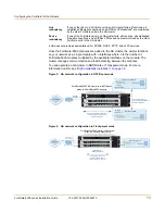
Page 12: ...or more FortiGate 5000 modules in a FortiGate chassis into an HA cluster The HA cluster can operate in active active mode or active passive mode An active active HA cluster can increase virus scanning throughput by using load balancing to distribute virus scanning to all of the FortiGate units in the cluster Both HA modes provide supports link redundancy and device redundancy Note When clustering ...

Page 13: ... session failover for PPPoE DHCP PPTP and L2TP services Device redundancy If one of the FortiGate units in an HA cluster fails all functions all established firewall connections and all IPSec VPN sessions are maintained by the other FortiGate units in the HA cluster FortiGate 5001SX HA cluster in in NAT Route mode in a FortiGate 5020 chassis Route mode policies controlling traffic between internal...

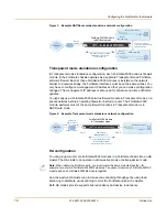
Page 14: ...nagement tool Use it to configure the administrator password the interface addresses the default gateway address and the DNS server addresses To connect to the CLI you require Serial connection between the FortiGate module and a management computer A terminal emulation application on the management computer If you are configuring the FortiGate antivirus firewall module to operate in Transparent mo...

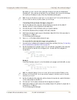
Page 15: ...e Connecting to the command line interface CLI on page 16 2 Set the IP address and netmask of port 1 to an IP address accessible by the computer with an ethernet connection and configure port 1 to allow HTTPS management connections config system interface edit port1 set ip IP_address netmask set allowaccess https end Example To set the IP address of port 1 to 192 168 20 99 and netmask to 255 255 2...

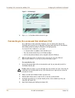
Page 16: ...erminal emulation software such as HyperTerminal for Windows To connect to the CLI 1 Connect the serial cable to the communications port of your computer and to the FortiGate Console port 2 Make sure that the FortiGate chassis is powered on 3 Start HyperTerminal enter a name for the connection and select OK 4 Configure HyperTerminal to connect directly to the communications port on your computer a...

Page 17: ... 5000 module in NAT Route mode see Configuring the FortiGate for the Network on page 11 This section describes Preparing to configure the FortiGate module in NAT Route mode Using the web based manager Using the command line interface Using the setup wizard Connecting the FortiGate unit to the network s Configuring the networks Next steps Preparing to configure the FortiGate module in NAT Route mod...

Page 18: ...__ Netmask _____ _____ _____ _____ Port 5 IP _____ _____ _____ _____ Netmask _____ _____ _____ _____ Port 6 IP _____ _____ _____ _____ Netmask _____ _____ _____ _____ Port 7 FortiGate 5001SX and FortiGate 5001FA2 only IP _____ _____ _____ _____ Netmask _____ _____ _____ _____ Port 8 FortiGate 5001SX and FortiGate 5001FA2 only IP _____ _____ _____ _____ Netmask _____ _____ _____ _____ Network setti...

Page 19: ...information you require for your PPPoE configuration Using the web based manager You can use the web based manager for the initial configuration of the FortiGate 5000 module You can also continue to use the web based manager for all FortiGate unit settings For information about connecting to the web based manager see Connecting to the web based manager on page 14 Configuring basic settings After c...

Page 20: ...l network usually the Internet Adding the default route also defines which interface is connected to an external network The default route is not required if the interface connected to the external network is configured using DHCP or PPPoE 1 Go to System Router Static 2 If the Static Route table contains a default route IP and Mask set to 0 0 0 0 select the Delete icon to delete this route 3 Selec...

Page 21: ...ure interfaces 1 Log in to the CLI 2 To set the IP address and netmask of port1 enter config system interface edit port1 set ip address_ip netmask end Example To set the IP address of port1 to 192 168 20 99 and netmask to 255 255 255 0 enter config system interface edit port1 set ip 192 168 20 99 255 255 255 0 end 3 To set the IP address and netmask of port2 enter config system interface edit port...

Page 22: ...ther settings for each of the FortiGate interfaces To configure DNS server settings Set the primary and secondary DNS server IP addresses Enter config system dns set primary address_ip set secondary address_ip end Example config system dns set primary 293 44 75 21 set secondary 293 44 75 22 end To add a default route Add a default route to configure where the FortiGate 5000 module sends traffic th...

Page 23: ...the default you can use the setup wizard to add the administration password configure the internal interface address choose either a manual static or a dynamic DHCP or PPPoE address for the external interface add a default route for the external interface add the DNS server IP addresses add the DHCP server settings and IP addresses add various internal server IP addresses including web IMAP POP3 S...

Page 24: ...mputers on your internal network Internal servers Web Server _____ _____ _____ _____ SMTP Server _____ _____ _____ _____ POP3 Server _____ _____ _____ _____ IMAP Server _____ _____ _____ _____ FTP Server _____ _____ _____ _____ If you provide access from the Internet to a web server SMTP server POP3 server IMAP server or FTP server installed on an internal network add the IP addresses of the serve...

Page 25: ...e 5002FB2 module connect interfaces 1 6 to gigabit copper ethernet networks Figure 7 FortiGate 5001SX example NAT Route mode connections Note If you change the IP address of the interface you are connecting to you must connect through a web browser again using the new address Browse to https followed by the new IP address of the interface If the new IP address of the interface is on a different su...

Page 26: ...t mode If you want to install the FortiGate 5000 module in NAT Route mode see NAT Route mode installation on page 17 If you want to install two or more FortiGate 5000 modules in HA mode see High availability installation on page 32 For more information about installing the FortiGate 5000 module in Transparent mode see Configuring the FortiGate for the Network on page 11 This section describes Prep...

Page 27: ... manager change the IP address of the management computer to 10 10 10 2 Connect to the internal interface and browse to https followed by the Transparent mode management IP address The default FortiGate Transparent mode management IP address is 10 10 10 1 To change the Management IP 1 Go to System Network Management 2 Enter the management IP address and netmask that you recorded in Table 4 on page...

Page 28: ... the management interface through a router make sure that you have added a default gateway for that router to the management IP default gateway field Using the command line interface As an alternative to the web based manager or setup wizard you can begin the initial configuration of the FortiGate 5000 module using the command line interface CLI To connect to the CLI see Connecting to the command ...

Page 29: ...55 255 0 end 3 Confirm that the address is correct Enter get system manageip The CLI lists the management IP address and netmask To configure DNS server settings 1 Set the primary and secondary DNS server IP addresses Enter config system dns set primary address_ip set secondary address_ip end Example config system dns set primary 293 44 75 21 set secondary 293 44 75 22 end To configure the default...

Page 30: ...the management computer to 10 10 10 2 Connect to the internal interface and browse to https followed by the Transparent mode management IP address The default FortiGate Transparent mode management IP address is 10 10 10 1 To start the setup wizard 1 Select Easy Setup Wizard the middle button in the upper right corner of the web based manager 2 Use the information that you gathered in Table 4 on pa...

Page 31: ...e connect interfaces 1 to 4 to gigabit fiber optic ethernet networks or copper gigabit networks depending on the SPF interfaces that yo have purchased Connect interfaces 5 to 8 to gigabit copper ethernet networks For the FortiGate 5002FB2 module connect interfaces 1 6 to gigabit copper ethernet networks Figure 8 FortiGate 5001SX example Transparent mode connections PWR ACC STA IPM CONSOLE USB 1 2 ...

Page 32: ... as heartbeat devices Port 9 and port 10 are only used for HA cluster communication and are not physically accessible These interfaces are not visible on the web based manager but they are visible on the CLI Configuring FortiGate 5000 modules for HA operation A FortiGate HA cluster consists of two or more FortiGate 5000 module with the same HA configuration This section describes how to configure ...

Page 33: ...he units in the cluster get the same virtual MAC address This virtual MAC address is set according to the group ID Group ID MAC Address 0 00 09 0f 06 ff 00 1 00 09 0f 06 ff 01 2 00 09 0f 06 ff 02 3 00 09 0f 06 ff 03 63 00 09 0f 06 ff 3f If you have more than one HA cluster on the same network each cluster should have a different group ID If two clusters on the same network have same group ID the d...

Page 34: ...raffic to the next available cluster module Weighted Round Robin Weighted round robin load balancing Similar to round robin but weighted values are assigned to each of the modules in a cluster based on their capacity and on how many connections they are currently processing For example the primary module should have a lower weighted value because it handles scheduling and forwards traffic Weighted...

Page 35: ...lose connectivity with the FortiGate module as the negotiation takes place 10 Repeat this procedure for all the FortiGate 5000 modules in the cluster Once all of the modules are configured continue with Connecting the cluster to your networks on page 37 Configuring HA in Transparent mode Ensure you switch the FortiGate 5000 module to Transparent mode before configuring the HA cluster To configure ...

Page 36: ... interface CLI on page 16 2 Change the host name config system global set hostname name_str end To configure the FortiGate 5000 module for HA operation 1 Configure HA settings Use the following command to Set the HA mode Set the Group ID Change the unit priority Enable override master Enter an HA password Select an active active HA schedule config system ha set mode a a a p standalone set groupid ...

Page 37: ...so connect all matching interfaces in the cluster to the same hub or switch which connects to your network For clusters within a FortiGate 5020 the FortiGate 5000 modules are connected to each other on the chassis backplane You must also connect each module to your network You must connect all matching interfaces in the cluster to the same hub or switch Then you must connect these interfaces to th...

Page 38: ... 5 6 7 8 Internet Internal Network Port 1 Port 3 Port 3 Port 1 Hub or Switch Hub or Switch Router PWR ACC STA IPM CONSOLE USB 1 2 3 4 5 6 7 8 PWR ACC STA IPM CONSOLE USB 1 2 3 4 5 6 7 8 PWR ACC STA IPM CONSOLE USB 1 2 3 4 5 6 7 8 1 2 2 3 4 5 ShMC 1 ShMC POWER ON MANAGEMENT SYSTEM E1 ZRE LED MODE 15 14 13 12 11 10 9 8 7 6 5 4 3 2 1 0 E2 OK CLK INT EXT FLT HOT SWAP RESET FLT CONSOLE E T H O R S 2 3 ...

Page 39: ...interface heartbeat device and monitoring configuration and the FortiGate host name For more information about configuring a cluster see the FortiGate Administration Guide Clustering FortiGate 5000 series chassis The FortiSwitch 5003 module provides full HA clustering capabilities to provide inter chassis communication The FortiSwitch 5003 acts as the switch providing automatic connection through ...

Page 40: ... the hour minute second month day and year as required 7 Select Apply To use NTP to set the FortiGate date and time 1 Go to System Config Time 2 Select Synchronize with NTP Server to configure the FortiGate unit to use NTP to automatically set the system time and date PWR ACC STA IPM CONSOLE USB 1 2 3 4 5 6 7 8 PWR ACC STA IPM CONSOLE USB 1 2 3 4 5 6 7 8 PWR ACC STA IPM CONSOLE USB 1 2 3 4 5 6 7 8...

Page 41: ... in a single session without re entering your contact information You can configure the FortiGate 5000 modules to automatically keep virus grayware and attack definitions up to date To configure virus attack and spam definition updates 1 Go to System Maintenance Update Center 2 Select Refresh to test the FortiGate 5000 module connectivity with the FortiProtect Distribution Network FDN To be able t...

Page 42: ...42 01 28011 0259 20060210 Fortinet Inc Next steps Configuring the FortiGate for the Network ...

Page 43: ...ame firmware version Reverting to a previous firmware version Use the web based manager or CLI procedure to revert to a previous firmware version This procedure reverts the FortiGate 5000 module to its factory default configuration Installing firmware images from a system reboot using the CLI Use this procedure to install a new firmware version or revert to a previous firmware version To use this ...

Page 44: ...ee the FortiGate Administration Guide Upgrading the firmware using the CLI To use the following procedure you must have a TFTP server that the FortiGate 5000 module can connect to To upgrade the firmware using the CLI 1 Make sure that the TFTP server is running 2 Copy the new firmware image file to the root directory of the TFTP server Note Installing firmware replaces the current antivirus and at...

Page 45: ... message This operation will replace the current firmware version Do you want to continue y n 6 Type y The FortiGate 5000 module uploads the firmware image file upgrades to the new firmware version and restarts This process takes a few minutes 7 Reconnect to the CLI 8 To confirm that the new firmware image is successfully installed enter get system status 9 Update antivirus and attack definitions ...

Page 46: ... FortiGate login This process takes a few minutes 7 Log into the web based manager 8 Go to System Status and check the Firmware Version to confirm that the firmware is successfully installed 9 Restore your configuration For information about restoring your configuration see the FortiGate Administration Guide 10 Update antivirus and attack definitions For information about antivirus and attack defi...

Page 47: ...mple if the TFTP server s IP address is 192 168 1 168 execute ping 192 168 1 168 5 Enter the following command to copy the firmware image from the TFTP server to the FortiGate 5000 module execute restore image name_str tftp_ipv4 Where name_str is the name of the firmware image file and tftp_ip is the IP address of the TFTP server For example if the firmware image file name is FGT_300 v280 build158...

Page 48: ...fault settings You can use this procedure to upgrade to a new firmware version revert to an older firmware version or re install the current firmware version For this procedure you access the CLI by connecting to the FortiGate console port using a null modem cable install a TFTP server that you can connect to from port8 The TFTP server should be on the same network as port8 Before beginning this p...

Page 49: ...ule execute reboot The FortiGate 5000 module responds with the following message This operation will reboot the system Do you want to continue y n 7 Type y As the FortiGate 5000 modules starts a series of system startup messages is displayed When one of the following messages appears FortiGate 5000 module running v2 x BIOS Press Any Key To Download Boot Image FortiGate 5000 module running v3 x BIO...

Page 50: ...ess Enter The following message appears Enter TFTP server address 192 168 1 168 10 Type the address of the TFTP server and press Enter The following message appears Enter Local Address 192 168 1 188 11 Type an IP address that can be used by the FortiGate 5000 module to connect to the FTP server The IP address can be any IP address that is valid for the network that the interface is connected to Ma...

Page 51: ... to a previous firmware version for example reverting from FortiOS v2 80 to FortiOS v2 50 you might not be able to restore your previous configuration from the backup up configuration file Testing a new firmware image before installing it You can test a new firmware image by installing the firmware image from a system reboot and saving it to system memory After completing this procedure the FortiG...

Page 52: ...ress Any Key To Download Boot Image FortiGate 5000 module running v3 x BIOS Press any key to display configuration menu 7 Immediately press any key to interrupt the system startup If you successfully interrupt the startup process one of the following messages appears FortiGate 5000 module running v2 x BIOS Enter TFTP Server Address 192 168 1 168 Go to step 10 FortiGate 5000 module running v3 x BIO...

Page 53: ...he firmware image file to the FortiGate 5000 module and messages similar to the following appear FortiGate 5000 module running v2 x BIOS Do You Want To Save The Image Y n Type N FortiGate 5000 module running v3 x BIOS Save as Default firmware Run image without saving D R or Save as Default firmware Backup firmware Run image without saving D B R 13 Type R The FortiGate image is installed to system ...

Page 54: ...168 1 168 5 Enter the following command to restart the FortiGate 5000 module execute reboot As the FortiGate 5000 module starts a series of system startup messages are displayed When of the following message appears Press any key to enter configuration menu 6 Immediately press any key to interrupt the system startup If you successfully interrupt the startup process the following message appears G ...

Page 55: ...are image that you previously installed When you switch the FortiGate 5000 module to the backup firmware image the FortiGate 5000 module operates using the configuration that was saved with that firmware image If you install a new backup image from a reboot the configuration saved with this firmware image is the factory default configuration If you use the procedure Restoring the default settings ...

Page 56: ...e B Boot with backup firmware and set as default Q Quit menu and continue to boot with default firmware H Display this list of options Enter G F B Q or H 4 Type B to load the backup firmware image The FortiGate 5000 module loads the backup firmware image and restarts When the FortiGate 5000 module restarts it is running the backup firmware version and the configuration is set to factory default ...

Page 57: ...nd attack definition updates and registering the FortiGate 5000 module The factory default protection profiles can be used to apply different levels of antivirus protection web content filtering spam filtering and IPS to the network traffic that is controlled by firewall policies NAT Route mode network configuration Transparent mode network configuration Firewall configuration Protection profiles ...

Page 58: ...0 0 0 Administrative Access Ping Port 8 FortiGate 5001SX and FortiGate 5001FA2 only IP 0 0 0 0 Netmask 0 0 0 0 Administrative Access Ping Network Settings Default Gateway for default route 192 168 100 1 Interface connected to external network for default route port2 Default Route A default route consists of a default gateway and the name of the interface connected to the external network usually t...

Page 59: ...parent mode Table 8 Factory default Transparent mode network configuration Administrator account User name admin Password none Management IP IP 10 10 10 1 Netmask 255 255 255 0 DNS Primary DNS Server 207 194 200 1 Secondary DNS Server 207 194 200 129 Administrative access Port 1 HTTPS Ping Port 2 Ping Port 3 Ping Port 4 Ping Port 5 Ping Port 6 Ping Port 7 FortiGate 5001SX and FortiGate 5001FA2 onl...

Page 60: ...erent traffic services to use the same or different protection profiles Protection profiles can be added to NAT Route mode and Transparent mode firewall policies The FortiGate 5000 module comes pre configured with four protection profiles Strict To apply maximum protection to HTTP FTP IMAP POP3 and SMTP traffic You may not use the strict protection profile under normal circumstances but it is avai...

Page 61: ... Select Reset to factory default 3 Select Apply Restoring the default settings using the CLI To reset the default settings 1 Connect to the CLI using the null modem cable and FortiGate console port 2 Enter the following command to restart the FortiGate 5000 module execute reboot As the FortiGate 5000 modules starts a series of system startup messages are displayed When the following message appear...

Page 62: ...owing message appears G Get firmware image from TFTP server F Format boot device B Boot with backup firmware and set as default Q Quit menu and continue to boot with default firmware H Display this list of options Enter G F B Q or H 4 Type B to load the backup firmware image The FortiGate 5000 module loads the default firmware image and restarts ...

Page 63: ...30 firmware installing 48 re installing current version 48 reverting to an older version 48 upgrading to a new version 44 upgrading using the CLI 44 46 upgrading using the web base manager 44 45 61 FortiGate 5001FA2 introduction 7 FortiGate 5001SX introduction 7 FortiGate 5002FB2 introduction 7 FortiGate 5020 chassis 6 FortiGate 5050 chassis 6 FortiGate 5140 chassis 6 Fortinet Knowledge Center 9 F...

Page 64: ...umentation 9 technical support 9 time zone 40 Transparent mode changing to 28 configuring the default gateway 29 default settings 59 management IP address 29 U upgrading firmware 44 firmware using the CLI 44 46 firmware using the web based manager 44 45 61 W web based manager connecting to 17 wizard setting up firewall 19 23 27 30 starting 19 24 27 30 ...

Reviews: