background image

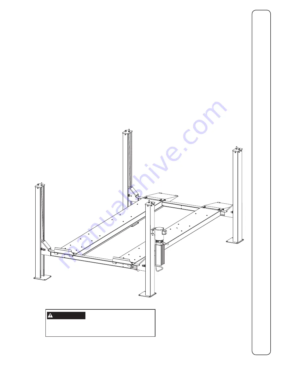
RSM4T

Capacity 4082 kg (9000 lbs)

2041kg (4500 lbs) per axle

Maximum Wheelbases: 3861mm (152")

Minimum Wheelbase At Rated Capacity: 2515mm (99")

 IN20534

Rev. C 9/10/2010

© September 2012 all rights reserved. 


CO8347    

I

N

S

T

A

L
L

A

T

I

O

N


I

N

S

T

R
U
C

T

I

O

N

S

I

N

S

T

A

L
L

A

T

I

O

N


I

N

S

T

R
U
C

T

I

O

N

S

IMPORTANT

Reference ANSI/ALI ALIS, 

Safety Requirements for 

Installation and Service of Automotive Lifts 

before installing lift.

Summary of Contents for RSM4T

Page 1: ...ated Capacity 2515mm 99 IN20534 Rev C 9 10 2010 September 2012 all rights reserved CO8347 I N S T A L L A T I O N I N S T R U C T I O N S I N S T A L L A T I O N I N S T R U C T I O N S IMPORTANT Reference ANSI ALI ALIS Safety Requirements for Installation and Service of Automotive Lifts before installing lift ...

Page 2: ...it width 3277mm 129 Column height 2221mm 87 7 16 Width of runways 508mm 20 Height of runways 127mm 5 Width between runways 1000mm 39 3 8 Lift Capacity 4082 kg 9000 lbs 4731mm 186 1 4 4070mm 160 1 4 4299mm 169 1 4 4500mm 177 3 16 772mm 30 3 8 5337mm 210 1 8 508mm 20 2413mm 95 2718mm 107 3023mm 119 3277mm 129 2221mm 87 7 16 1962mm 77 1 4 127mm 5 508mm 20 1000mm 39 3 8 4191mm 165 ...

Page 3: ...alcohol use that will impair your ability to install or operate your lift DANGER Improper installation or improper use of your lift could cause serious injury or death Read installation instructions and owner s manual thoroughly before installing or operating your lift Unloading And Unpacking Your Lift The components for your lift are heavy The runways for these lifts weigh in excess of 182 kg 400...

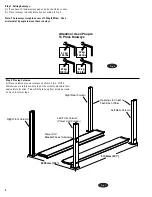
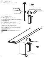
Page 4: ...umn Step 1 Setting Runways A If you haven t read previous pages go back and do so now B Place runways in desired location according to Fig 3 Note The runways weigh in excess of 182kg 400 lbs Use a minimum of 4 people to move these runways Fig 2 Fig 3 Step 2 Placing Columns A Place columns around runways as shown Fig 3 NOTE Dimensions are reference only to get the columns placed in their approximat...

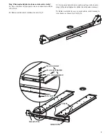
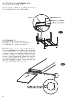
Page 5: ...C Place crossbeams on ground between columns IMPORTANT NOTE ORIENTATION OF CROSSBEAMS THE SIDE OF THE CROSSBEAM WITH THE SHORT SIDE COVER GOES Ensure Latch Bar Goes Between Crossbar and Retainer Rub Block TOWARDS THE INSIDE OF THE LIFT THE CROSSBEAM WITH THE FULL LENGTH SIDE COVER GOES TO THE OUTSIDE THIS IS CRITICAL FOR CABLE INSTALLATION D Slide columns into crossbeams until it hits the rub bloc...

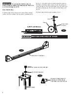
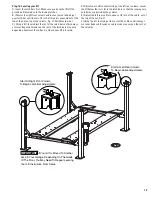
Page 6: ...6 Make sure latch bar jam nut is located far enough down the latch bar stud to allow you to fully insert the column top plate in the top of the column B After column top plates have been installed adjust latch bar nut and latch bar jam nut as shown Fig 7 Column Top Plate Top Of Column Latch Bar Stud Ø20 Flat Washer M20 Latch Bar Jam Nut Ø12 Washer On Each Side Of Column M12 X 35 Hex Head Bolt 4 On...

Page 7: ...clarity A Use a minimum of 2 people to raise crossbeam assemblies to first lock B Remove inside short crossbeam covers Fig 8 C Using a mechanical device such as pulley or winch come along fully extend hydraulic cylinder located under runway D Being careful not to cross or pinch cables install runway to crossbeams as shown Fig 9 Fig 10 Fig 8 ...

Page 8: ...ilure to do so will cause damage to your lift Step 6 Cable Routing A Route cables from runway to each column When running cable across the crossbeam be sure cables run behind center IMPORTANT MAKE SURE CABLES DO NOT GET CROSSED bar Fig 11 Run cables up each column keeping the cables on the inside of the slack cable actuators Fig 10 You will need to remove the Sheave Pins Fig 9 and Sheave Fig 10 in...

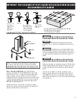
Page 9: ...u DO NOT have enough embedment Drill 3 4 dia holes in concrete floor using holes in column base plate as a guide See Figures above for hole depth hole spacing and edge distance requirements IMPORTANT PUSH COLUMNS UP TIGHT AGAINST RUB BLOCKS BEFORE DRILLING OR ANCHORING LIFT COLUMNS CAUTION DO NOT install on asphalt or other similar unstable surfaces Columns are supported only by anchors in floor I...

Page 10: ...lbow onto power unit Fig 14 B Install hydraulic hose onto 90 elbow of power unit and fitting in side of runway Fig 14 Step 10 Adding Hydraulic Fluid To Power Unit A Remove fill breather cap and fill with Dexron III ATF only to fill line on tank The capacity of the tank is approximately 12 liters Note If fill breather cap is lost or missing replace with original equipment replacement part IMPORTANT...

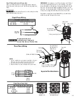
Page 11: ...tachment L1 PE L2 L3 MOTOR 1 3 5 2 4 6 DRUM SWITCH 3 Phase Supply NOTES 1 Unit not suitable for use in unusual conditions Contact Rotary for moisture and dust environment duty unit 2 Control Box must be field mounted to power unit 3 Motor rotation is counter clockwise from top of motor Three Phase Power Unit MOTOR OPERATING DATA TABLE THREE PHASE LINE VOLTAGE RUNNING MOTOR VOLTAGE RANGE 208 240V 5...

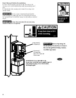
Page 12: ...e button on power unit Fig 15 and raise the runways up to a comfortable working height approximately waist high B Push down on the lowering valve to lower the runways onto locking latches IMPORTANT You have not yet completed the locking latch release linkage assembly at this point Your lift will only lower onto the locking latches Do not lift the runway too high until you complete step 13 IMPORTAN...

Page 13: ... Remove outer crossbeam covers B Insert latch bar through crossbeam assembly and through left side runway latch bar supports Rod inserts from rear of lift and comes out near the power unit on the front of the lift C Install Cam to Latch Release Bar as shown Fig 16 Fig 17 D Install Latch Release Handle to Cam as shown Fig 17 E Install Linkages to Cam as shown Fig 18 Cam should sit straight up and d...

Page 14: ...es C Push down on the lowering valve to lower lift Note Without pulling up on the lock lever the lift will only lower onto the locking latches Any time you lower the lift you will have to raise your lift off of the locking latches approximately 1 inch and pull up on the lock lever to allow the locking latches to clear the slots in the latch bars Releasing the lock lever will re engage the locks Th...

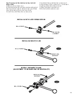
Page 15: ...f the cable out of the top of the nut Fig 21 F Using the 4 ft level adjust the rest of the cables until runways are level Exposed threads on cable studs may vary on the rest of the columns Step 16 Leveling your lift A Level the latch bars first Make sure you have the lift off the ground and lowered onto the locking latches B Start at the right front column and loosen jam nut and adjust your latch ...

Page 16: ...ch for 3 phase motor graphic Installer Please return this booklet to literature package and give to lift owner operator Thank You Trained Operators and Regular Maintenance Ensures Satisfactory Performance of Your Lift Contact Your Nearest Authorized Parts Distributor for Genuine Replacement Parts See Literature Package for Parts Breakdown ...

Reviews: