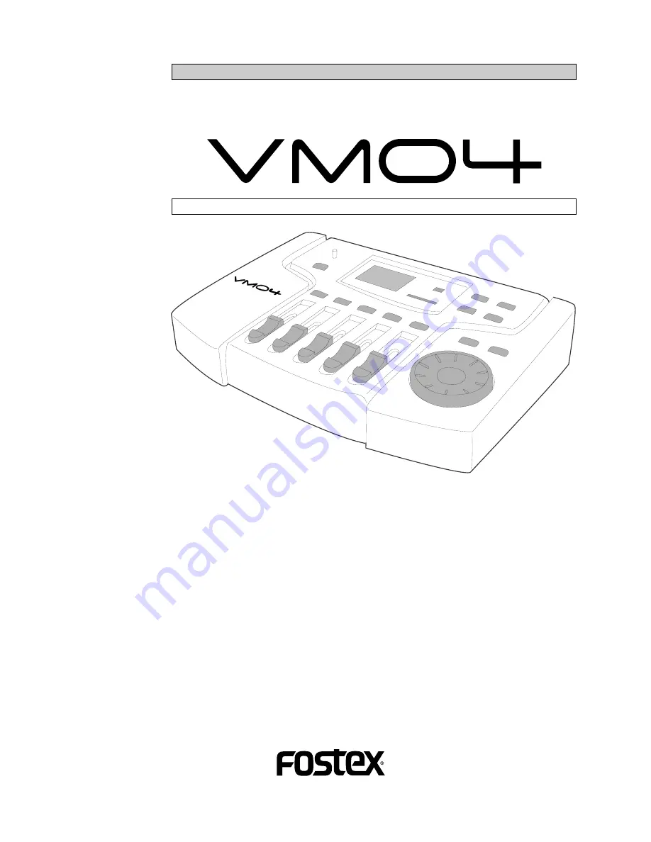
background image

Model

Owner’s manual

4CH DIGITAL MIXER WITH DSP EFFECTS

Introduction

Thank you very much for having purchased the Fostex VM04.
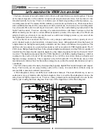
This unit is a digital mini-mixer so the internal signal processing is all done digitally.
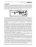
Its input section consists of four analog input channels including two that can take a
microphone. The output section, in addition to normal analog outputs like two channel
stereo outputs and a headphone output, also has an S/P DIF digital output via an optical
format with a 44.1kHz sampling frequency and a 20 bit resolution.
Its internal Buss consists of a two channel Stereo L/R and also an independent Effect Buss.
The VM04  also incorporates an internal high quality digital effect (1in/ 2out) employing
the A. S. P. (Fostex Advanced Signal Processing Technology)*, which is newly developed by
Fostex.  It can provide a wide variety of Effect sounds.  You can also store all the mix settings
you have made in the Scene Memories and recall them instantly.
The VM04 is a light and compact piece of precision sound technology which offers high
quality sound performance and considerable scope for experimentation.
To fully exploit all of its many useful features and functions, we recommend you read this
manual first before you start using the VM04.

* See page 18 for more details of the A. S. P. (Fostex Advanced Signal Processing Technology).

Summary of Contents for VM04

Page 1: ...s of a two channel Stereo L R and also an independent Effect Buss The VM04 also incorporates an internal high quality digital effect 1in 2out employing the A S P Fostex Advanced Signal Processing Technology which is newly developed by Fostex It can provide a wide variety of Effect sounds You can also store all the mix settings you have made in the Scene Memories and recall them instantly The VM04 ...

Page 2: ... that the grounding or polarization means of an appliance is not defeated 12 Power Cord Protection Power supply cords should be routed so that they are not likely to be walked on or pinched by items placed upon or against them paying particular attention to cords at plugs convenience receptacles and the point where they exit from the appliance 13 Cleaning The appliance should be cleaned only as re...

Page 3: ...ure Locations with excessive moisture or dust Locations where direct sunlight falls for an extended time or near a stove or other source of heat Locations where electrical voltage varies Unstable locations or where there is heavy vibration Near strong magnetic fields on top of a television or speaker Table of Contents Precautions 3 Let sexaminetheVM04inmoredetail 4 1 Input Section 5 2 Buss Section...

Page 4: ...s the standard digital audio signal And the VM04 is capable of transferring the mixed audio signal in digital to other digital equipment like the Fostex D 5 DAT recorder The digital audio signal that the VM04 handles is a 44 1kHz sampling frequency which is common to the audio CD and 20 bit resolution of the AD DA conversion Analog to Digital and Digital to Analog conversion This is superior to th...

Page 5: ... in digital At the next point on the diagram there is an arrow pointing upwards and to the right and labeled METER The VM04 extracts the signal level at this point and displays it in the Channel 1 level meter on the LCD Display Liquid Crystal Display This point is sometimes called Pre Fader or Pre EQ Move on to the next section EQ You will see a rectangle labeled 100Hz and 10kHz There are controls...

Page 6: ...edicated switches for this purpose but you select it by entering the CHANNEL EDIT mode If you look at the second line after the FADER you will see that the base of arrow touching it is connected to the EFFECT SEND volume control This control adjusts the audio level to be sent to the EFFECT in each channel This control is not available on the VM04 control panel but you can set it by entering the CH...

Page 7: ...tion Some large mixers may have a selector switch so that it is possible to choose which part of the signal flow will be monitored In the case of the VM04 the monitor output will always send exactly the same signal to the STEREO OUT as to the Headphones 4 Effect Section The destination of the signal from the Effect Buss line is the Effect section You can treat the Effect section as if it is an ind...

Page 8: ...ir of headphones to the socket and control the volume level by using the control knob 1 Names and Functions 5 STEREO OUT L R jacks 6mm Phone Jack Un Balance To send a mixed audio signal to other equipment such as an MTR Stereo Monitor system or another mixer 6 RESET SW To reset the internal CPU See the Before Use section for more details 7 INPUT jacks 6mm Phone Jack Un Balance To connect the audio...

Page 9: ...ch function to adjust and display on the LCD Display and VIEW Status Indicator 16 DATA ENCODER Use this dial to set the various values in each mode 17 MASTER FADER Use this to adjust the output level at the STEREO OUT jack 18 INPUT FADERs Use this to adjust the input level on the individual channel 19 CHANNEL EDIT key Press this key to enter the CHANNEL EDIT MODE See CHANNEL EDIT MODE page 15 20 F...

Page 10: ...powering ON OFF timing or some electro magnetic noise such as thunder and lightning IF the unit does not power up properly even after several attempts to power ON press the RESET SW to reset the CPU If you want to clear all the Scenes stored in the past you can use the same method here All the memories and Setup contents will return to the factory default setting by pressing the SW 2 4 Internal ba...

Page 11: ...3 2 1 MAX MIN SCENE No 0 6 12 24 OL 1 2 3 4 L R 1 2 3 4 MIN L R MAX EFF HI LO PAN EQ VIEW LEVEL FADER ADJUST ENTER EXIT DATA STORE RECALL SCENE PARAMETER TYPE EFFECT SETUP MAX MIN MAX MIN MAX MIN DIGITAL MINI MIXER VM04 3 Applications Application 1 To expand theAnalog channel input for recording You will be able to record up to 4 Analog channels on the FD 8 at once by connecting the VM04 S P DIF o...

Page 12: ...R 1 2 3 4 MIN L R MAX EFF HI LO PAN EQ VIEW LEVEL FADER ADJUST ENTER EXIT DATA STORE RECALL SCENE PARAMETER TYPE EFFECT SETUP MAX MIN MAX MIN MAX MIN DIGITAL MINI MIXER VM04 START ID SEARCH SEARCH BLANK CUE AUTO START CAL MIN MAX CH2 CAL MIN MAX CH1 LEVEL INPUT SAMPLING FREQ CLOCK INPUT GPI REMOTE DIGITAL 48kHz EXT OPTICAL ON 44 1kHz INT ANALOG OFF LOCAL 9P REMOTE SHTL JOG SCRUB RAM REPEAT PREVIEW...

Page 13: ...illuminated dots See CHANNEL EDIT MODE page 15 Channel Fader display This section will numerically indicate the INPUT Fader position of the channel you choose in the CHANNEL EDIT MODE on a range from 0 to 99 But there will be no numbers showing at the initial setting See CHANNEL EDIT MODE page 15 Master Fader display This part will numerically indicate the Master Fader position on a range from 00 ...

Page 14: ... When the indicator is showing 80 the MASTER Fader will be at the nominal setting Useful info When you move the INPUT and MASTER Faders their numerical positions will be digitally indicated And the actual sound will increase or decrease smoothly without any clicking or stepping noise interference The relationship between the Fader position and real gain is 0 80 0dB 99 6dB Caution If the FADER FIX ...

Page 15: ...ion You can use the VIEW key to change the item you want to adjust PAN EQ Lo EQ Hi EFF POST PRE PAN Press the EXIT key to quit the CHANNEL EDIT MODE You can go back to the Normal Mix mode Useful info The VIEW key works in reverse if youkeeppressingitforawhilerather than hitting it once PAN POST PRE EFF EQ Hi EQ Lo PAN Channel Fader display This will numerically indicate the current Channel 1 INPUT...

Page 16: ...single dot and move upwards to MAX Similarly if you turn the dial counter clockwise the display will show 1dB 18dB the bass sound will become quieter and the indicator will move downwards to MIN Useful info The specification of the EQ Lo is the Shelving Type Equalization and its control frequency is 100Hz 18dB 6 3 EQ Hi setting 1 Press the VIEW key so that the HI dot is flashing on the VIEW Status...

Page 17: ...6dB See EFFECT MODE page 18 for more details of the internal digital Effect 6 5 EFFECT POST PRE setting 1 PresstheVIEWkeyjustoncemoreattheprevious EFFECT SEND setting There will be no change on the VIEW Status Indicator but the LCD Display will show the following message Character section This will display 1 P P Pst This means that you can now choose the Channel 1 EFFECT SEND in either the Post Fa...

Page 18: ...e to establish high density and transparent sounds Before operating the EFFECT MODE let s briefly discuss the Reverb Delay Chorus and Flanger effect functions which are integrated in the VM04 Reverb The Reverb effect consists of various reflection echo sounds mixed together Just as when you clap your hands in a tunnel for example you hear the sound lingering after you have stopped clapping your ha...

Page 19: ...se You can see the following Effect types one after another Only the indicators are changing at this stage You can choose just one type from among them at any one time 1 Hall Rev1 11 Stadium1 2 Hall Rev2 12 Stadium2 3 Hall Rev3 13 Delay 4 Hall Rev4 14 Delay Rev 5 Room Rev1 15 L R Delay 6 Room Rev2 16 L R Rev 7 Room Rev3 17 Chorus 8 Room Rev4 18 Cho Rev 9 Plate Rev1 19 Flanger 10 Plate Rev2 20 Fla ...

Page 20: ...vTm 0 1 9 9 Sec 4 Chorus related Effect 17 Chorus is the Chorus related Effect This has three parameters 1 Chorus Level ChoLv 0 99 2 Modulation Frequency Rate 0 1 9 9 Hz 3 Chorus Depth Depth 0 99 The parameters available in each Effect type The available parameters differ according to the Effect type These are discussed here 5 Combined Chorus Reverb Effect 18 Cho Rev is the Effect you get when Cho...

Page 21: ...el adjustment for an independent effect unit 2 Reverb Time setting Press the EFFECT PARAMETER key once again The character section will read RevTm 3 5 This means you can now adjust the Reverb Time Its current setting will be 3 5 second which is the default setting of the Hall Rev 1 Turn the DATA ENCODER clockwise The reverb time value will increase on the display and also the reverb sound on actua...

Page 22: ...ss the SCENE STORE key when you want to store the setting that you have made The key will light up and the Scene number display will start flashing You can enter the Scene Store Mode from whichever mode you are in For example Normal Mix Mode Channel Edit Mode or Effect Mode 2 Rotate the DATA ENCODER and choose a Scene number from 01 to 20 on which you want to store the setting 3 Press the ENTER ke...

Page 23: ...o is concerned the audio level has also been recalled according to the stored Fader setting However at the same time the FADER ADJUST key will start flashing As the VM04 Faders do not move automatically this is the way the VM04 indicates that it has detected some discrepancy between the physical Fader position now and when the Scenes were stored At this stage as the VM04 is already in the Normal M...

Page 24: ...dition to the method discussed in Scene Recall 8 2 This mode will recall the Scenes in numerical order 1 Press the SCENE RECALL key and keep holding it The key will light up and at the same time the EFFECT TYPE key and EFFECT PARAMETER key will start flashing Note the cursor description and above the EFFECT TYPE key and EFFECT PARAMETER key If you press the EFFECT TYPE key the Scene numbers will c...

Page 25: ...r Effect mode EQ VIEW CHANNEL EDIT MASTER 4 3 2 1 MAX MIN SCENE No 0 6 12 24 OL 1 2 3 4 L R 1 2 3 4 MIN L R MAX EFF HI LO PAN EQ VIEW LEVEL FADER ADJUST ENTER EXIT DATA STORE RECALL SCENE PARAMETER TYPE EFFECT SETUP MAX MIN MAX MIN MAX MIN CH MASTER 9 SETUP Mode The VM04 has a Setup mode This is described in detail here 1 2 4 Blink 1 Press the EFFECT TYPE key and EFFECT PARAMETER key together Both...

Page 26: ...OFF This completes the set up and the VM04 will return to the Normal Mix mode The Setup will be kept even after powering OFF Channel Fader Recall chRCL ON Default setting OFF If you set this mode to OFF when recalling the Scenes the INPUT Channel Faders will not recall their stored positions but their settings before recalling the Scene will remain effective The INPUT Faders will work normally in ...

Page 27: ...elving Type 10kHz 18dB LO Shelving Type 100Hz 18dB FREQUENCY RESPONCE 20Hz 20kHz TYPICAL Specifications DYNAMIC RANGE 90dB TYPICAL A D converter 20bit 64 times Over Sampling Enhanced Dual Bit Delta Sigma D A converter 20bit 128 time Over Sampling Delta Sigma SAMPLING FREQUENCY 44 1kHz DIGITAL OUTPUT 44 1kHz 16 bit linear TOTAL HARMONIC DISTORTION 0 01 TYPICAL CROSSTALK 70dB or more 1kHz GENERAL DC...

Reviews: