background image


BANCO SEGA 254 mm 

TABLE SAW 254 mm 


Modello Fox F36-522 

Fox model F36-522 


MANUALE DI ISTRUZIONI / USER MANUAL  

Summary of Contents for F36-522

Page 1: ...BANCO SEGA 254 mm TABLE SAW 254 mm Modello Fox F36 522 Fox model F36 522 MANUALE DI ISTRUZIONI USER MANUAL ...

Page 2: ...le originale Original manual 3 26 ENGLISH EN Manuale tradotto dall originale Manual translated from the original 27 50 DICHIARAZIONE DI CONFORMITA DECLARATION OF CONFORMITY 51 ESPLOSO EXPLODED VIEW 52 SCHEMA ELETTRICO WIRING DIAGRAM 55 ...

Page 3: ... Assemblaggio delle estensioni del piano di lavoro Pag 18 Montaggio dei binari anteriori Pag 18 Montaggio della guida parallela Pag 19 Montaggio del supporto dello spingipezzo Pag 19 Fissaggio al suolo Pag 19 Avvio del banco sega Pag 20 Interruttore di protezione Pag 20 Frenatura della lama Pag 20 Manovella di salita e discesa della lama Pag 21 Ghiera di inclinazione della lama Pag 21 Pomello di b...

Page 4: ...i rotanti in movimento 3 ferimenti per contatto con parti spigolose 4 ferimenti per eiezioni di parti di utensile o di materiale in lavorazione 5 danni causati dal rumore 6 danni causati dall inalazione di polveri pericolose 7 ferimenti per utensili montati male Le attrezzature di sicurezza previste sulle macchine come le protezioni i carter gli spingipezzo i dispositivi di ritenuta i dispositivi ...

Page 5: ...olunghe elettriche previste per l esterno e che riportino delle indicazioni in merito 8 Siate vigili Osservate attentamente quello che fate abbiate buon senso Non utilizzate l utensile quando siete affaticati 9 Non utilizzate l utensile se siete sotto l effetto di medicinale alcol droghe 10 Evitate l avvio accidentale Assicuratevi che l interruttore sia nella posizione di arresto prima di collegar...

Page 6: ...che le chiavi di serraggio e di regolazione siano state allontanate dall utensile prima di avviarlo 22 Controllate i particolari dell utensile per verificare che non ci siano parti danneggiate Prima di continuare ad utilizzare l utensile controllate tutti i dispositivi di sicurezza o qualsiasi altro pezzo che possa essere danneggiato in modo da assicurarvi che funzioni bene e che riesca ad effettu...

Page 7: ...LIZZATE MAI la guida di taglio parallela come guida di tranciatura per il taglio trasversale 10 FATE sempre avanzare il pezzo da tagliare contro la lama o l utensile 11 NON TENTATE MAI di sbloccare la lama senza prima arrestare l utensile Anche se volete interrompere il taglio mettete l interruttore in posizione di arresto e aspettate che la lama si fermi Intervenite solo con lama ferma e in manca...

Page 8: ...47 1 21 UTILIZZATE lame adatte al materiale da tagliare e che abbiano marcata una velocità maggiore di quella della macchina Quando si sostituisce la lama verificare che il diametro esterno e il diametro del foro siano giusti che la larghezza del taglio della lama non sia inferiore allo spessore del coltello divisore e che lo spessore del corpo lama non sia superiore a quella del coltello divisore...

Page 9: ...ure riconsegnarla al rivenditore al momento dell acquisto di una nuova apparecchiatura di tipo equivalente in ragione di uno ad uno L adeguata raccolta differenziata per l avvio successivo dell apparecchiatura dismessa al riciclaggio al trattamento ed allo smaltimento ambientalmente compatibile contribuisce ad evitare possibili effetti negativi sull ambiente e sulla salute e favorisce il reimpiego...

Page 10: ...fornita Se non entra nella presa fate installare una presa appropriata da un elettricista qualificato Un collegamento mal fatto del conduttore della messa a terra dell attrezzo può comportare il rischio di scarica elettrica Il conduttore la cui guaina isolante è verde con o senza linea gialla è il conduttore della messa a terra Se risulta necessaria la riparazione o la sostituzione del cavo di ali...

Page 11: ... 0 45 con lama diritta a 0 si possono tagliare spessori di legno fino a 80 mm mentre con lama inclinata si può tagliare uno spessore fino a 55 mm La macchina è dotata di sufficiente stabilità ma ha comunque la possibilità in caso di necessità di essere fissata al suolo LIMITI DI UTILIZZO NON tagliate dei pezzi di legno di spessore superiore agli 80 mm NON tagliate il metallo la pietra la gomma la ...

Page 12: ...sua ventilazione si consiglia di tenerlo controllato e puliti i passaggi dell aspirazione per le lame di utilizzare tipi silenziati e di tenerle sempre in perfetta efficienza e per il materiale da tagliare di usare le lame giuste e di tenere sempre ben bloccati i particolari da tagliare per gli ingranaggi si deve solo verificare periodicamente il loro consumo controllando il loro gioco sulla lama ...

Page 13: ... estensioni del piano di lavoro e il basamento sono forniti come optional Togliere la sega e tutti i vari componenti dall imballo verificare che non manchi nulla e che non ci sia niente di danneggiato Nel caso fossero presenti parti difettose o rovinate non utilizzarle per non compromettere l efficienza e la sicurezza dell utensile Rivolgersi ad un centro assistenza autorizzato per la sostituzione...

Page 14: ...lama 3 Pomello di bloccaggio della lama 4 Spingipezzo 5 Goniometro 6 Lama 7 Coltello divisorio 8 Protezione della lama 9 Guida parallela 10 Impugnatura di regolazione e di bloccaggio della guida parallela 11 Manovella di salita e discesa DESCRIZIONE DEL BANCO SEGA ...

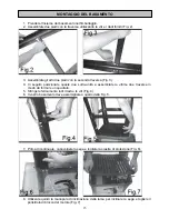
Page 15: ...e sotto unità e assemblate le ultime due traverse in modo da formare un quadrato 5 Stringete fermamente tutti i dadi e le viti Fig 4 6 Il vostro basamento deve assomigliare a quello della Fig 5 7 Prima di continuare capovolgete la sega e togliete la piastra di protezione Fig 6 8 Utilizzate quindi la manopola di inclinazione della lama per inclinare la sega e togliere il polistirolo di blocco del m...

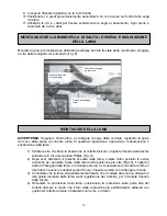
Page 16: ...ips Fig 9 2 Dopo aver sbloccato il pomello di salita della lama ruotate l altro pomello in senso antiorario per spostare l asse della lama nella posizione più alta Fig 10 Togliete il dado di fissaggio della lama e la flangia esterna Successivamente montate la lama i denti devono essere orientati verso il fronte Fissate la lama con la flangia e il dado 3 Controllate che la lama sia perfettamente fi...

Page 17: ...due fessure del coltello divisorio Fig 11 Non stringetele completamente per il momento Regolate il coltello in modo che ci sia uno spazio tra i 2 e i 5 mm Fig 12 tra la lama e il coltello divisorio e controllate anche l allineamento tra il coltello divisorio e la lama usando una riga Stringete le viti esagonali In seguito controllate ancora una volta che la lama sia perfettamente fissata e rimonta...

Page 18: ...ondella a molla e il dado 1 Montate il binario sinistro sulla parte anteriore dell estensione sinistra e sulla parte anteriore del piano di lavoro con le viti M5 x 12 le rondelle M5 le rondelle a molla e i dadi corrispondenti 2 Verificate il corretto funzionamento della guida parallela posizionando la guida nella scanalatura del binario anteriore e stringendo la manopola della guida in senso antio...

Page 19: ...mpugnatura di bloccaggio Assicuratevi sempre che la guida parallela sia perfettamente bloccata sulla tavola prima di iniziare a lavorare Fig 18 I due supporti dello spingipezzo devono essere montati nella parte laterale della macchina con 4 viti M3x6 i dadi M3 e le rondelle di arresto Fig 18a Il fissaggio al suolo può essere fatto utilizzando 4 tasselli per cemento Si fanno 4 fori nel cemento in c...

Page 20: ...izionato a lato dell interruttore Quando interviene fa scattare l interruttore e ferma la sega A questo punto si deve lasciare raffreddare la macchina qualche minuto poi premere il pulsante di ripristino manuale e successivamente il tasto verde dell interruttore per fare ripartire la lama Se non parte aspettare ancora qualche altro minuto e riprovare Se la macchina continua a non avviarsi scollega...

Page 21: ...l inclinazione della lama Fig 22 Per allentare il pomello ruotate in senso antiorario Per le operazioni di inclinazione o di regolazione della lama allentate questo pomello Al contrario prima di ogni operazione di taglio assicuratevi che sia perfettamente bloccato La lama deve essere bloccata in posizione prima di utilizzare il goniometro Assicuratevi sempre che la lama sia perfettamente bloccata ...

Page 22: ...ati regolate l angolo di taglio del goniometro allentandone e stringendone la vite e appoggiate il vostro pezzo di legno da lavorare Fig 24 Utilizzate il goniometro sul lato nel quale non rischia di interferire con la protezione della lama Il taglio obliquo è come un taglio trasversale ma con la lama inclinata ad grado particolare Regolate la lama sull angolo desiderato Utilizzate il goniometro in...

Page 23: ...e il coltello divisore sia perfettamente allineato con la lama Per la rifilatura dei pezzi grandi o dei pannelli utilizzate sempre dei carrelli per sostenere i pezzi di legno Esercitate una leggera pressione e utilizzate sempre lo spingipezzo fino a che il pezzo non sia perfettamente tagliato Fig 27 E necessario utilizzare sempre uno spingipezzo se le vostre mani si trovano a meno di 125 mm dalla ...

Page 24: ...re e scollegate la sega dalla corrente togliendo la spina del cavo dalla presa di corrente prima di qualsiasi regolazione riparazione manutenzione o sostituzione della lama Qualsiasi danneggiamento delle protezioni o anomalia riscontrata nel funzionamento o nel corso del controllo della sega deve essere riparata immediatamente da personale qualificato per quel tipo di intervento Prima di ogni util...

Page 25: ...di corrente nella presa in cui è inserito il cavo di alimentazione Cavo di alimentazione difettoso Motore in avaria o spazzole da sostituire Vibrazioni sulla macchina Pomello di fissaggio dell inclinazione non bloccato Lama fissata male Il legno si annerisce durante il taglio Utensile non adeguatamente affilato Utensile montato al contrario Usura rapida degli utensili Utensile non adeguatamente af...

Page 26: ...ostante queste attenzioni un utensile dovesse guastarsi la riparazione deve essere fatta da un centro riparazioni autorizzato Delta France L elenco dei centri assistenza è reperibile presso i vari punti vendita o telefonando a 051 6946469 o inviando una richiesta all indirizzo di posta elettronica info fox machines com ASSISTENZA ...

Page 27: ...handle 40 Assembly of the saw blade 40 Assembly of the riving knife 41 Assembly of workbench extensions 42 Assembly of front rails 42 Assembly of the rip fence 43 Assembly of pusher s holder 43 Fixing to the ground 43 Start ot the table saw 44 Protective thermal cut out 44 Braking of the saw blade 44 Height adjustment handle 45 Angle adjustment ferrule 45 Angle locking knob 45 Goniometer 45 Crossc...

Page 28: ...e to contact with angular parts 4 injuries due to the ejection of tool parts or of the material you are processing 5 injuries due to noise The probability of risk can be reduced by the machine safety equipment of the machines as for example the protections the blade case the clamping the stoppage and the personal protection devices as protective goggles the dust mask ear plugs protective shoes and...

Page 29: ...ing have good sense Do not use the machine if you are tired 33 Do not use the machine if you are have taken medicines alcohol drugs 34 Avoid accidental starts Be sure that the switch is on the OFF position before inserting the plug into the socket 35 Wear appropriate clothing Do not wear loose sleeved garments or pieces of jewellery which may get caught in the moving parts For outdoor use we recom...

Page 30: ...ify that there are not any damages Before using the machine check if the safety devices or any other parts are damaged in order to be sure that it works properly and that it can accomplish the tasks for which it has been designed Check that the moving parts are aligned do not stop and are not broken Check the assembly and any other condition that can influence the functioning of the machine Any pa...

Page 31: ...p fence for cross cutting 35 PUSH ALWAYS the piece you have to cut through the saw blade or the tool 36 DO NOT TRY to remove the saw blade before switching off the tool Also if you want to stop cutting put the switch on the OFF position and wait for the blade to stop rotating You can perform tasks of any kind only if the blade is still and the machine is disconnected from the power supply 37 DO NO...

Page 32: ...in compliance with EN 847 1 standard 46 USE only correct saw blades which are suitable to the material to be cut and on which the marked speed is higher than the one of the machine When changing the blade check if external diameter and bore diameter are correct that cutting width and the blade body are not thinner than the riving knife width Transport the saw blade inside its case 47 CHANGE the pl...

Page 33: ...d electronic goods or alternatively hand it over to the relative dealer at the moment of purchasing a new appliance of the same type on a basis of a one to one ratio Differentiated disposal to enable possible recycling or environmentally compatible elimination of the appliance helps to limit undesirable effects on health and environment and promotes the reuse and or recycling of the materials that...

Page 34: ... is not correctly connected the risk of electric shock can occur The conductor which has the green insulating jacket with or without a yellow line is the earthing conductor If you must repair or change the supply cable do not connect the earthing conductor to a low tension terminal Consult a qualified electrician or a person in charge of the maintenance if you have not understood or you have some ...

Page 35: ... machine is stable enough however it is possible to fix it to the ground USE LIMITS DO NOT cut wood wider than 80 mm DO NOT cut metal stone rubber plastics chalk glass wool etc DO NOT cut stubs or irregular wood pieces DO NOT use this machine for ribbing or moulding DO NOT assemble other tools or different saw blades DO NOT use it as a portable tool or a not fixed machine DO NOT modify the machine...

Page 36: ...its ventilation system and the aspiration passages As far as the saw blade is concerned it is preferable to use silenced type of blades and to keep them in good conditions We recommend to use the correct saw blade and to keep firmly the workpiece to be cut As far as the gears are concerned you have only to check periodically their consumption by verifying the play with the saw blade Noise levels a...

Page 37: ...ions and the base are provided as extras Remove the table saw and all the parts from the package check if there are any missing or damaged parts If you find any faulty or damaged parts do not use them in order not to endanger the efficiency and the safety of the machine To change faulty parts consult an after sales centre To make the table saw work perfectly you must assemble the various parts for...

Page 38: ...le of the saw blade 14 Locking knob of the saw blade 15 Pusher 16 Goniometer 17 Saw blade 18 Riving knife 19 Saw blade protection 20 Rip fence 21 Rip fence s adjustment and locking handle 22 Height adjustment handle MACHINE DESCRIPTION ...

Page 39: ...his two units and assemble the last two crossbars in order to form a square 16 Firmly tighten all the nuts and screws Fig 4 17 Your base must look like the one of Fig 5 18 Before keeping on assembling the machine turn the table saw upside down and remove the protective plate Fig 6 19 Then use the angle adjustment lever to tilt the saw and remove the polystyrene that blocks the engine Fig 7 ASSEMBL...

Page 40: ...t by loosening the 8 Phillips flat head screws Fig 9 8 After unlocking the height knob turn the other handle anti clockwise to move the axle of the blade in its highest position Fig 10 Remove the locking nut of the saw blade and the external flange Then assemble the saw blade teeth must point towards the front side of the machine Fix the blade with the flange and the nut 9 Check that the blade is ...

Page 41: ...in order that the two hexagonal screws pass through the two slots of the riving knife Fig 11 Do not completely tighten them yet Adjust the knife in order that there is a space from 2 to 5 mm Fig 12 between the blade and the riving knife by using a ruler Tighten the hexagonal screws then check again that the saw blade is perfectly fixed and re assemble the bench insert Afterwards assemble the prote...

Page 42: ...ng then the washer the spring washer and the nut 4 Assemble the left rail to the front side of the left extension and to the front side of the workbench with the M5 x 12 screws the M5 washers the spring washers and the corresponding nuts 5 Check the correct functioning of the rip fence by placing the fence in the front rail groove and by tightening the its handle anti clockwise to lock it Loosen t...

Page 43: ... lower the lock handle Be sure that the rip fence is perfectly locked on the workbench before starting working Fig 18 You must assemble the two pusher s holders to the lateral side of the machine with 4 M3x6 screws the M3 nuts and the lock washers Fig 18a You can fix the machine to the ground by using 4 cement anchors You must drill 4 holes in the cement by the 4 holes of the base feet then you fi...

Page 44: ... avoid to burn the motor It is located one the switch s side When it starts it sets off the switch and stops the saw Then you must let the machine cool down some minutes then press the manual overload reset button and afterwards the green button of the switch to start again the saw blade again If it does not start wait still some minutes and try again If the machine does not start disconnect it fr...

Page 45: ...e knob again By using this device you can lock saw blade angle Fig 22 To loosen the knob turn it anti clockwise Use this knob for all angle and adjustment operations On the contrary before any cutting work be sure that it is perfectly blocked The blade must be blocked in the desired position before using the goniometer Be always sure that the saw blade is perfectly blocked before using the machine...

Page 46: ...cut adjust the cutting angle of the goniometer by loosening and tightening its screw and press the workpiece against it Fig 24 Use the goniometer on the side on which it does not risk to interfere with the protective cap Angle cut is a crosscut with the angled blade Adjust the saw blade on the desired angle Use the goniometer in one of the grooves in order that it does not interfere with the prote...

Page 47: ...blade and that the riving knife is perfectly aligned to the saw blade To trim big workpieces or panels always use a trolley to support the workpieces Exert a light pressure and always use the pusher until the piece is completely cut Fig 27 You must always use a pusher if your hands are less than 125 mm from the saw blade The pusher is a safety device that allows you to keep your hands and fingers ...

Page 48: ...able that you clean accurately the machine to remove all dust piles CAUTION Before any adjustment repair or maintenance work and before changing the blade switch off the machine and disconnect it form any current source by removing the plug from the socket In case you find out any damage to the protection devices or irregularities while processing or checking the machine you must get it repaired i...

Page 49: ...e guide of the housing 14 Screw the cover of the carbon brushes and check the functioning of the engine The saw does not start The electric current is missing in the socket to which the supply cable is connected The supply cable is faulty The engine is damaged or the carbon brushes must be replaced Machine vibrations The inclination lock handle is not correctly tightened The blade is not correctly...

Page 50: ... the safest and most modern productive methods However if a tool get damaged it must be repaired by an authorised after sales centre You can call the phone number 051 6946469 or by sending a request to the e mail address info fox machines com AFTER SALES SERVICE ...

Page 51: ...ioni contenute nelle Direttive CEE 98 37 CEE 2006 42 2004 108 2006 95 CE DECLARATION OF CONFORMITY OF THE MANUFACTURER Femi SpA Via Salieri 33 35 40024 Castel S Pietro Terme BO Italia Tel 39 051 6946469 Fax 39 051 6946470 Declares that the TABLE SAW F36 522 is in compliance with the regulations included in the Directives CEE 98 37 CEE 2006 42 2004 108 2006 95 15 11 2009 Il Presidente del Consiglio...

Page 52: ...52 F36 522 BANCO SEGA 254MM TABLE SAW 254 MM ...

Page 53: ...36522 60 18 F36522 18 61 F36522 61 19 F36522 19 62 F36522 62 20 F36522 20 63 F36522 63 21 F36522 21 64 F36522 64 22 F36522 22 65 F36522 65 23 F36522 23 66 F36522 66 24 F36522 24 67 F36522 67 25 F36522 25 68 F36522 68 26 F36522 26 69 F36522 69 27 F36522 27 70 F36522 70 28 F36522 28 71 F36522 71 29 F36522 29 72 F36522 72 30 F36522 30 73 F36522 73 31 F36522 31 74 F36522 74 32 F36522 32 75 F36522 75 3...

Page 54: ...4 149 F36522 149 105 F36522 105 150 F36522 150 106 F36522 106 151 F36522 151 107 F36522 107 152 F36522 152 108 F36522 108 153 F36522 153 109 F36522 109 154 F36522 154 110 F36522 110 155 F36522 155 111 F36522 111 156 F36522 156 112 F36522 112 157 F36522 157 113 F36522 113 158 F36522 158 114 F36522 114 159 F36522 159 115 F36522 115 160 F36522 160 116 F36522 116 161 F36522 161 117 F36522 117 162 F365...

Page 55: ...55 SCHEMA ELETTRICO WIRING DIAGRAM ...

Reviews: