background image

CAUTION

Read all precautions and instruc-

tions in this manual before using

this equipment. Save this manual

for future reference.

QUESTIONS?

If you have questions, or if parts are

damaged or missing,

DO NOT

CONTACT THE STORE; please

contact Customer Care.

IMPORTANT: Please register this

product (see the limited warranty

on the back cover of this manual)

before contacting Customer Care.

CALL TOLL-FREE:

1-800-999-3756

Mon.–Fri. 6 a.m.–6 p.m. MT

Sat. 8 a.m.–4 p.m. MT

ON THE WEB:

www.iconservice.com

USER'S MANUAL

Model No. SFTL19609.0

Serial No.

Write the serial number in the space

above for reference.

www.iconfitness.com

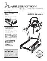
Serial Number

Decal

Summary of Contents for SFTL19609.0

Page 1: ...THE STORE please contact Customer Care IMPORTANT Please register this product see the limited warranty on the back cover of this manual before contacting Customer Care CALL TOLL FREE 1 800 999 3756 Mon Fri 6 a m 6 p m MT Sat 8 a m 4 p m MT ON THE WEB www iconservice com USER S MANUAL Model No SFTL19609 0 Serial No Write the serial number in the space above for reference www iconfitness com Serial ...

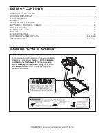
Page 2: ...RAWING 28 ORDERING REPLACEMENT PARTS Back Cover LIMITED WARRANTY Back Cover FREEMOTION is a registered trademark of ICON IP Inc 2 This drawing shows the locations of the warning decals If a decal is missing or illegible call the telephone number on the front cover of this manual and re quest a free replacement decal Apply the decal in the location shown Note The decals may not be shown at actual s...

Page 3: ... cord into a surge suppres sor not included and plug the surge sup pressor into a grounded circuit capable of carrying 15 or more amps No other appliance should be on the same circuit Do not use an extension cord 12 Use only a single outlet surge suppressor that meets all of the specifications described on page 12 To purchase a surge suppressor see your local FREEMOTION dealer or call the telephon...

Page 4: ... safely lift 45 lbs 20 kg to move the incline trainer 22 Do not change the incline of the incline trainer by placing objects under the incline trainer 23 Inspect and properly tighten all parts of the incline trainer regularly 24 Never insert or drop any object into any opening on the incline trainer 25 DANGER Always unplug the power cord immediately after use before cleaning the incline trainer an...

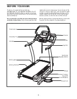
Page 5: ...e see the front cover of this manual To help us assist you note the product model number and serial number before contacting us The model number and the location of the serial number decal are shown on the front cover of this manual Before reading further please familiarize yourself with the parts that are labeled in the drawing below BEFORE YOU BEGIN 5 Handrail Console Fan Key Clip Reset Off Circ...

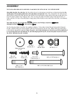
Page 6: ...a soft cloth and a mild non abrasive cleaner Assembly requires the included hex keys and your own Phillips screwdriver adjustable wrench and scissors Use the drawings below to identify the assembly hardware The number in parentheses below each drawing is the key number of the part from the PART LIST near the end of this manual The number after the parentheses is the quantity needed for assembly No...

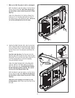
Page 7: ... the Upright is positioned as shown See the inset drawing Tie the wire tie in the Right Upright 79 around the end of the Upright Wire 78 Then pull the other end of the wire tie until the Upright Wire is routed completely through the Right Upright Attach the Right Upright 79 to the Base 80 with two 3 8 x 3 1 2 Patch Bolts 5 and two 3 8 Star Washers 8 Start both Patch Bolts before tightening either ...

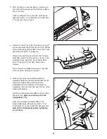
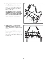
Page 8: ...oles Separate the Console Back from the Console Cover 87 Discard the Screws Press the Left and Right Accessory Trays 99 100 out of the Console Cover 87 99 100 34 5 Have a second person hold the Handrail Assembly 88 near the Handrail Brackets 76 Insert the Upright Wire 78 through the indicated hole in the bottom of the Handrail Assembly and out of the hole near the top of the Handrail Assembly Set ...

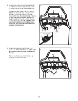
Page 9: ...and four 1 4 Star Washers 9 Start all four Bolts before firmly tightening any of them Remove the two plastic ties and the wire tie 6 88 86 3 9 3 9 78 Wire Tie 90 91 Hole Plastic Tie Plastic Tie Hole 7 Set the Console Cover 87 on the Handrail Assembly 88 Make sure that the Console Cover is oriented with the ties toward the bottom as shown Attach the Console Cover 87 with four 8 x 3 4 Screws 1 Start...

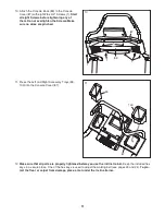
Page 10: ...The con nectors should slide together easily and snap into place If they do not turn one con nector and try again IF THE CONNECTORS ARE NOT CONNECTED PROPERLY THE CONSOLE MAY BE DAMAGED WHEN THE POWER IS TURNED ON 8 85 87 97 91 78 Hole 90 78 Console Wire Wires 9 Attach the Console 85 with four 8 x 3 4 Screws 1 Start all four Screws before tight ening any of them Do not overtighten the Screws Tight...

Page 11: ...o wires are pinched 12 Make sure that all parts are properly tightened before you use the incline trainer Keep the included hex keys in a secure place One of the hex keys is used to adjust the walking belt see pages 23 and 24 To pro tect the floor or carpet from damage place a mat under the incline trainer 11 Press the Left and Right Accessory Trays 99 100 into the Console Cover 87 11 100 99 87 ...

Page 12: ...lfunc tion or break down grounding provides a path of least resistance for electric current to reduce the risk of elec tric shock This product is equipped with a cord having an equipment grounding conductor and a grounding plug Plug the power cord into a surge suppressor and plug the surge suppressor into an appropriate outlet that is properly installed and grounded in accordance with all local co...

Page 13: ...ad personalized workouts and to track and analyze your workout re sults on the iFit Live website You can also listen to your favorite workout music or audio books with the consoleʼs premium stereo sound system while you get in shape To turn on the power see page 14 To use the man ual mode see page 14 To use a calorie burn work out or an all terrain trails workout see page 16 To use a set a goal wo...

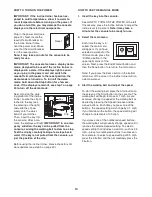
Page 14: ... just the position of the clip Before using the incline trainer please check for soft ware updates see step 5 on page 20 HOW TO USE THE MANUAL MODE 1 Insert the key into the console See HOW TO TURN ON THE POWER at the left If necessary press the Incline buttons to adjust the incline level to 0 percent Note It may take a minute for the console to be ready for use 2 Select the main menu Each time th...

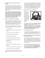
Page 15: ...el by pressing the Volume increase and decrease buttons on the con sole To reset the console press the iFit Menu button in the upper right corner of the screen To pause the workout press the Pause button To continue the workout press the Resume button or the Start but ton To end the current workout and select a new workout press the New Workout button To end the workout press the End Workout butto...

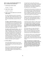
Page 16: ...or con secutive segments During the workout the profile will show your progress Press the Display increase and decrease buttons repeatedly to view the profile The red line will indicate the current segment of the workout The height of the current segment indicates the in cline setting for the current segment At the end of the first segment of the workout a se ries of tones will sound If a differen...

Page 17: ...ber of calories you will burn dur ing the workout 4 Start the workout Press the Start Workout button to start the work out A moment after you press the button the walk ing belt will begin to move Hold the handrails and begin walking The workout will function in the same way as the manual mode see pages 14 and 15 If the speed or incline setting is too high or too low at any time during the workout ...

Page 18: ...ation If this equipment does cause harmful interference to radio or television reception which can be determined by turning the equipment off and on the user is en couraged to try to correct the interference by one of the following measures Reorient or relocate the receiving antenna Increase the separation between the equipment and the receiver Connect the equipment into an outlet on a circuit dif...

Page 19: ...atic IP address and or a static domain name server DNS To use encryption press the Use Encryption but ton and then press the Use Encryption check box to check it Select the encryption type and enter the password Press the arrow buttons to view ad ditional entry boxes To return to the main menu press the Cancel button When you are finished press the Submit button To use numbers or other characters ...

Page 20: ...ngs mode To exit the settings mode press the Back button HOW TO USE THE CALIBRATION MODE The console features a calibration mode that allows you to calibrate the incline and speed of the incline trainer and to update the console software 1 Select the settings mode Insert the key into the console see step 1 on page 14 Select the main menu see step 2 on page 14 Then press the i button in the lower r...

Page 21: ...he incline trainer back until it rolls freely on the wheels CAUTION To decrease the possibil ity of injury or of damage to the incline trainer do not lift the incline trainer by the plastic belly pan Do not pull on the console Carefully roll the incline trainer on the wheels to the desired location and then lower it to the level position CAUTION To reduce the risk of injury use extreme cau tion wh...

Page 22: ...g use SOLUTION a Check the reset off circuit breaker see the drawing above If the circuit breaker has tripped wait for five minutes and then press the switch to the reset position b Make sure that the power cord is plugged in If the power cord is plugged in unplug it wait for five minutes and then plug it back in c Remove the key from the console Reinsert the key into the console d If the incline ...

Page 23: ... SOLUTION a Use only a single outlet surge suppressor that meets all of the specifications described on page 12 b If the walking belt is overtightened incline trainer per formance may decrease and the walking belt may be come damaged Remove the key and UNPLUG THE POWER CORD Using the hex key turn both idler roller bolts counterclockwise 1 4 of a turn When the walking belt is properly tightened you...

Page 24: ...ower cord insert the key and run the incline trainer for a few minutes Repeat until the walking belt is centered b If the walking belt slips when walked on first remove the key and UNPLUG THE POWER CORD Using the hex key turn both idler roller bolts clockwise 1 4 of a turn When the walking belt is correctly tightened you should be able to lift each edge of the walking belt 3 to 4 in 8 to 10 cm off...

Page 25: ...e If your goal is to strengthen your cardiovascular system you must perform aerobic exer cise which is activity that requires large amounts of oxygen for prolonged periods of time For aerobic ex ercise adjust the intensity of your exercise until your heart rate is near the highest number in your training zone WORKOUT GUIDELINES Warming Up Start with 5 to 10 minutes of stretching and light exercise...

Page 26: ...Belt 41 1 Magnet 42 1 Drive Roller Pulley 43 2 Belt Guide 44 1 Walking Platform 45 1 Left Foot Pad 46 1 Right Foot Pad 47 1 Idler Roller 48 1 Walking Belt 49 1 Front Hood 50 1 Power Cord 51 1 Grommet 52 1 Belly Pan Cover 53 1 Reset Off Circuit Breaker 54 1 Belly Pan 55 1 Reed Switch 56 1 Reed Switch Clamp 57 1 Left Rear Cushion 58 1 Frame 59 1 Belly Pan Plate 60 1 Left Front Cushion 61 1 Front Bel...

Page 27: ...le Back 103 1 Filter 104 1 PC Power Supply 105 1 Key Clip 4 White Wire M F 6 Blue Wire M F 10 Brown Wire 2F Userʼs Manual Note Specifications are subject to change without notice For information about ordering replacement parts see the back cover of this manual These parts are not illustrated ...

Page 28: ... 21 24 24 23 23 25 25 13 31 31 35 35 35 35 35 35 35 35 35 36 39 42 41 48 44 43 49 47 43 52 54 14 50 51 53 15 40 35 35 1 1 18 1 46 45 19 19 19 19 19 19 19 19 36 18 18 18 18 18 EXPLODED DRAWING A Model No SFTL19609 0 R1209B 28 ...

Page 29: ... SFTL19609 0 R1209B 1 1 1 1 1 1 17 17 17 17 18 56 20 22 22 26 27 13 29 31 31 32 32 32 33 33 55 59 57 60 58 61 63 67 65 64 62 68 71 75 72 66 74 32 33 33 73 13 70 69 13 13 18 18 13 30 30 1 1 1 1 1 1 1 37 101 13 30 13 13 103 104 29 ...

Page 30: ...2 2 2 6 6 7 7 8 5 28 28 8 8 83 82 82 79 12 12 80 84 84 78 78 10 11 11 81 81 5 8 2 8 5 5 8 77 10 10 10 4 8 8 4 76 8 4 8 4 4 76 4 8 4 4 8 8 8 30 EXPLODED DRAWING C Model No SFTL19609 0 R1209B ...

Page 31: ...05 96 85 92 16 93 94 16 16 16 94 86 87 88 98 98 89 3 95 91 90 97 1 1 1 1 1 1 1 1 1 1 1 1 1 1 1 1 1 1 1 3 9 9 67 1 92 92 92 93 93 93 99 100 34 34 102 102 31 EXPLODED DRAWING D Model No SFTL19609 0 R1209B ...

Page 32: ... does not extend to any damage to a product caused by or attributable to freight damage abuse misuse improper or abnormal usage or repairs not provided by an ICON authorized service cen ter to products used for commercial or rental purposes or as store display models or to products trans ported or purchased outside the US No other warranty beyond that specifically set forth above is autho rized by...

Reviews: