background image

USA 1-800-374-4432 

www.frigidaire.com

Canada 1-800-265-8352

www.frigidaire.ca   

316495194

Important Safety Instructions ...............................  3

List of materials ................................................... 5

Electrical requirements ......................................... 5

Location requirements .......................................... 6

Product dimensions .............................................. 6

Venting Requirements .......................................... 7

Prepare the location ............................................. 8 

Install Range Hood (Ducted version) ..................... 10

Make Electrical Connection .................................... 11

Range Hood Use .................................................. 12

Range Hood Care ................................................. 13

Troubleshooting ................................................... 15 

Warranty Information ........................................... 16

August 2016

Summary of Contents for FHWC3050RS

Page 1: ...structions 3 List of materials 5 Electrical requirements 5 Location requirements 6 Product dimensions 6 Venting Requirements 7 Prepare the location 8 Install Range Hood Ducted version 10 Make Electrical Connection 11 Range Hood Use 12 Range Hood Care 13 Troubleshooting 15 Warranty Information 16 August 2016 ...

Page 2: ... range hood and Thank You for choosing our product We hope you consider us for future purchases PLEASE CAREFULLY READ AND SAVE THESE INSTRUCTIONS This Use Care Manual provides specific operating instructions for your model Use your every possible condition and situation that may occur Common sense and caution must be practiced when installing operating and maintaining any appliance Please record yo...

Page 3: ... by the manufacturer If you have questions contact the manufacturer Before servicing or cleaning the unit switch power off at service panel and lock service panel disconnecting means to prevent power from being switched on accidentally When the service disconnecting means cannot be locked securely fasten a prominent warning device such as a tag to the service panel Installation Work and Electrical...

Page 4: ...ose clothing The manufacturer declines all responsibility in the event of failure to observe the instructions given here for installation maintenance and suitable use of the product The manufacturer further declines all respon sibility for injury due to negligence and the warranty of the unit automatically expires due to improper mainte nance a b c d 1 2 3 4 IMPORTANT SAFETY INSTRUCTIONS WARNING T...

Page 5: ...al co and or tools designed and UL listed for joining copper to aluminum Follow the electrical connector manufacturer s recom mended procedure Aluminum copper connection must conform with local codes and industry accepted wiring practices Wire sizes and connections must conform with the rating of the appliance as specified on the model serial rating plate The model serial plate is located on the l...

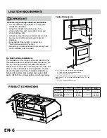
Page 6: ...R Part 328 formerly the Federal Standard for Mobile Home Construction and Safety Title 24 HUD Part 280 or when such standard is not applicable the stan dard for Manufactured Home Installation 1982 Manu factured Home Sites Communities and Setups ANSI A225 1 NFPA 501A or latest edition or with local codes Cabinet Dimensions B 30 76 2 cm min cabinet opening width for 30 76 2 cm models and 36 91 4 cm ...

Page 7: ...use Makeup Air Local building codes may require the use of makeup air systems when using ventilation systems greater than specified CFM of air movement The specified CFM varies from locale to locale Consult your HVAC professional for specific requirements in your area Venting Methods Vent system can terminate either through the roof or wall Use 3 x 10 8 3 x 25 4 cm rectangular with a maximum vent ...

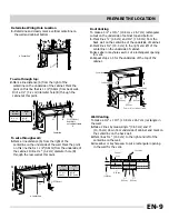
Page 8: ... surface Mark rear mounting screw hole locations wide filler strips Length and recess dimensions Four flat head wood screws or two 2 5 1 cm thickness determined by machine screws with washers and nuts to attach filler strips in locations shown Install framing for hood rear support If drywall is present using the rear mounting screw hole locations marked in the previous step cut away enough drywall...

Page 9: ...Dim A 30 36 models 8 5 8 21 9 cm Roof Venting To make a 4 x 10 10 8 cm x 26 7 cm rectangular cutout on the underside of cabinet top and bottom Mark lines 1 6 cm and 4 10 8 cm from the back wall on the centerline of the underside of cabinet Mark lines 5 13 3 cm to the right and left of the centerline on the underside of cabinet Use saber or keyhole saw to cut a rectangular opening for vent Repeat s...

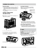
Page 10: ...ch other Remove the vent damper flap if vent knockout A rear rectangular vent knockout B Power Supply Cable Installation For direct wire installations run the home power supply cable according to the National Electric Code or CSA standards and local codes and ordinances 1 For roof installations remove the top rectangular For wall installations remove the NOTE Do not reconnect power until the insta...

Page 11: ...lectrical wire through the UL listed or CSA approved strain relief to make connections in the terminal box Tighten the strain relief screws Position the range hood so that the large end of the keyhole slots are over the mounting screws Then push the hood toward the wall so that the screws are in the neck of the slots Tighten the mounting screws making sure the screws are in the narrow neck of slot...

Page 12: ...per towels To avoid damage to the stainless steel do not use cleaners that contain chlorine Cleaning Method RANGE HOOD USE A B A C Knob Graphics Fan Icon HI MED LO OFF Knob Graphics Light Icon ON FRONT REAR OFF Light Fan The hood controls are located at the bottom front section of the unit D Control knobs Push in on knob to release and then rotate it counter clockwise for fan speeds Hi Med Lo Off ...

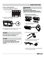
Page 13: ... OPEN Push in at the indicated area to open the vent grille The vent grille will hinge down for access to the grease filters and slide the panel back Squeeze LED lamp mounting clips and push down the LED lights as shown below WARNING Electrical Shock Haxzard Disconnect power before servicing Replace all parts and panels before operating Failure to do so can result in death or electrical shock NOTE...

Page 14: ...Replace with new LED lights WARNING Electrical Shock Haxzard Disconnect power before servicing Replace all parts and panels before operating Failure to do so can result in death or electrical shock Squeeze here Squeeze here P art number 5304503879 down the LED lights as shown below 3 Squeeze LED lamp mounting clips and push EN 14 ...

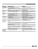
Page 15: ...sure the wires on light switch are connected properly The hood is not venting out properly 1 The hood might be hanging to high from the cook top 2 The wind from the opened windows or opened doors in the surrounding area are affecting the ventilation of the hood 2 Close all the windows and doors to eliminate the outside wind flow 3 Blockage in the duct opening or duct work 3 Remove all the blocking...

Page 16: ...horized service companies use of parts other than genuine Electrolux parts or parts obtained from persons other than authorized service companies or external causes such as abuse misuse inadequate power supply accidents fires or acts of God CUSTOMER S SOLE AND EXCLUSIVE REMEDY UNDER THIS LIMITED WARRANTY SHALL BE PRODUCT REPAIR OR REPLACEMENT AS PROVIDED HEREIN CLAIMS BASED ON IMPLIED WARRANTIES I...

Reviews: