background image

Summary of Contents for Professional PL36WC40EC

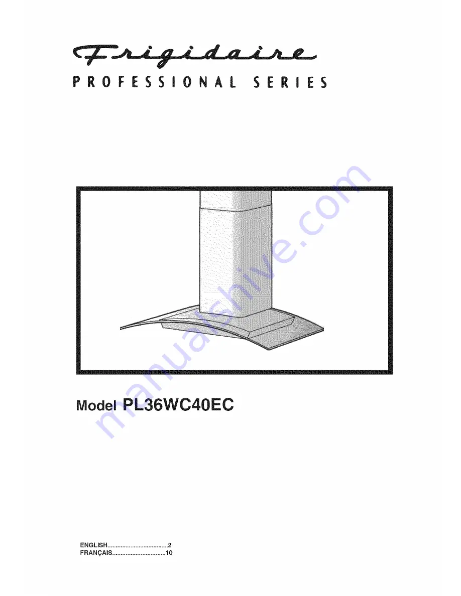
Page 1: ...PROFESSIONAL SERIES Model PL36WC40EC ENGLISH 2 FRAN _AmS 10 ...

Page 2: ...ppropriate for the size of the surface element _ WARNING TO REDUCE THE RISK OF INJURY TO PERSONS IN THE EVENT OFA RANGE TOP GREASE FIRE OBSERVE THE FOLLOWING 1 SMOTHER FLAMES with a close fitting lid cookie sheet or metal tray then turn off the burner BE CAREFUL TO PREVENT BURNS If the flames do not go out immediately EVACUATE AND CALL THE FIRE DEPARTMENT 2 NEVER PICK UP A FLAMING PAN You may be b...

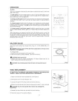
Page 3: ...n the grease filters Once the grease filters are cleaned and installed press in and hold the light switch button for approximately 2 seconds during the blink of the LED i o o o d P_ oFESS_ 0S_ _SE_I_S 011 im_ 1 0 blink l 2 HALOGEN BULBS This range hood requires two halogen bulbs Type JC 12Volt 20Watt Max G 4 Base _ WARNING Always switch off the electrical supply before carrying out any operation o...

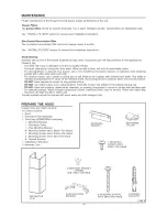
Page 4: ...ub lightly in direction of polishing lines or grain of the stainless finish Avoid using too much pressure which may mar the surface DO NOT allow deposits to remain for long periods of time DO NOT use ordinary steel wool or steel brushes Small bits of steel may adhere to the surface causing rust DO NOT allow salt solutions disinfectants bleaches or cleaning compounds to remain in contact with stain...

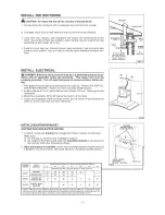
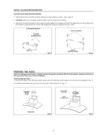
Page 5: ...eceptacle 18 to 22 above the bottom of the hood 4 Locate the receptacle within boundary shown and off center of the ductwork to allow for power cord plug and flue clearance INSTALL MOUNTING BRACKET DUCTED AND NON DUCTED HOODS 1 Construct wood wall framing that is flush with interior surface of wall studs Make sure a the framing is centered over installation location b the height of the framing wil...

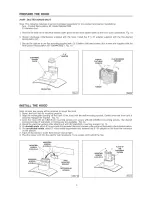
Page 6: ... wall and centered over the hood FLUE MOUNTING BRACKET 3 9 x 6 mm FLAT HEAD BRACKET SCREWS 265 6 mm DRYWALL ANCHORS 4 8x38mm MOUN_NG SCREWS PREPARE THE HOOD Note On stainless steel hoods carefully remove the plastic protective film from all exterior surfaces of the hood and decorative flues prior to final installation DUCTED HOODS ONLY 1 Remove the tape on the electrical system plate place the ele...

Page 7: ... its mounting position 2 Align the rectangular opening on the back of the hood with the wall mounting bracket Gently lower the hood until it securely engages the bracket Fig I4 3 Level the hood with 2 3 9xg 5mm mounting screws and secure with 2 4 8x38mm mounting screws Use drywall anchors provided if wal studs or framing are not available Fig 14 4 Mount the electrical system plate attaching it wit...

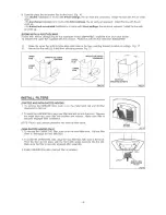
Page 8: ...s Fig 17 UPPER UPPER FLUE VENTS UPPER FLUE VENTS CONCEALED FLUE_ EXPOSED LOWER FLUE _ UPPER FLUE FLUE 3 9xg 5rnm MOUNTING SCREWS iNSTALL FILTERS DUCTED AND NON DUCTED HOODS 1 To remove the GREASE filter push in on the metal latch tab and tilt filter downward to remove 2 To install the GREASE filter align rear filter tabs with slots in the hood Depress the metal latch tab push filter into position ...

Page 9: ...s to finish after installation 6 Replacement of light bulbs and or fluorescent tubes on models with these features EXCLUSIONS This warranty does not cover the following 1 CONSEQUENTIALORINCIDENTAL DAMAGESSUCH AS PROPERTY DAMAGEAND INCIDENTAL EXPENSES RESULTING FROM ANY BREACH OF THIS WRITTEN OR ANY IMPLI ED WARRANTY Note Some states do not allow the exclusion or limitation of incidental or consequ...

Page 10: ... _ la surface de votre element de cuisson d_ _ AVERTISSEMENTS POUR REDUIRE LES RISQUES DE DOMMAGESAUX PERSONNESAUCASOU VOTRECUISINIERE PRENDRAITFEU OBSERVEZ LES INSTRUCTIONS SUIVANTES 1 ETEINDRE LES FLAMMES _ I aide d un couvercle le plus hermetique possible une plaque g_ teaux ou un plateau en metal puis eteindre le brQleur ATTENTION NE PAS VOUS BRULER Si les flammes ne s eteignent pas immediatem...

Page 11: ...e nettoyees Apres avoir remonte les filtres anti graisse propres appuyez sur le bouton de la lumiere pendant 2 secondes environ au m6me temps les voyants lumineux clignotons i i O O O df O P R 6 F ES SIO N _ t SERI_S J Z imer I Nlill 2 AMPOULES HALOGENES Ce modele de hotte veut deux 2 ampoules halogenes Type JC 12Volt 20Watt Max G 4 Base ATTENTION Avant de proc_der a quelconque operation d_branche...

Page 12: ...u Frottez leg ement en suivant la direction du polissage ou du grain de I acier inoxydable Evitez de frotter trop fort afin de ne pas ab mer la surface NE LAISSEZ PAS les taches trop Iongtemps e N UTILISEZ PAS de Iaines d acier ordinaires ou des brosses en acier Des debris d acier pourraient adh er b la surface et causer de la rouilte NE PERMETTEZ PAS que des solutions saIees des desinfectants des...

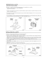
Page 13: ... prise de courant 18 a 22 au dessus du has de la hotte 4 Placez la prise dans les limites indiquees et en dehors du centre des systemes de gaines pour permettre une distance du cordon d alimentation et du carneau INSTALLATION SUPPORT DE FIXATION HOTTES CARE NEES OU NON CARENEES 1 Construisez une armature murale en bois affleuree avec une surface interieure de poteaux de cloison Assurez vous que a ...

Page 14: ...ntre au dessus de la hotte ETRIER DE SUPPORT 3 9 x 6 rnm VIS D ASSEMBLAGE A TI_ T E PLATE J 265 6 mm OHEVILLES VIS D ASSEMBLAGE 4 8x38mm PREPARATION DE LA HOTTE Remarque si la hotte est en acier inoxydabie retirez pr_cautionneusement le film protecteur des surfaces ext_rieures et des carneaux d_coratifs avant de terminer I installation HOTTES CARENEES 1 Enlevez le ruban adhesif sur le panneau du s...

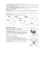
Page 15: ...oit ou elle sera installee 2 Alignez ouverture rectangulaire situee a I arriere de la hotte avec le support de fixation murale Abaissez lentement la hotte jusqu a ce qu elle s embo te avec le support Fig 14 3 Mettez la hotte b niveau au moyen des vis d assemblage 3 gxg 5mm et fixez la au moyen de deux 2 vis de montage 4 8x38mm Si vous ne disposez pas de poteaux de cloison ni d armature utilisez le...

Page 16: ...tage 3 9xg 5mm Fig 17 CARNEAU PRISES D AIR PRISES D AIR SUP RIEUR SUP_ RIEURES SUPC RIEURES VISIBLES DISSIMUL_ ES CARNEAU INFERIEUR _ INF_ RIEUR 3 9x9 5mm VIS DE MONTAGE iNSTALLATiON DES FILTRES CONFIGURATIONS CARENEES ET NON CARENEES 1 Pour retirer le filtre b GRAISSE attrapez la languette du taquet et abaissez la afin de degager le fittre de la hotte 2 Pour remettre le filtre a GRAISSE en place ...

Page 17: ...ur les modeles ayant ces caract istiques EXCLUSIONS Cette garantie ne couvre pas ee qui suit 1 DOMMAGES INDIRECTS OU ACCESSOIRES TELS QUE DOMMAGE ik LA PROPRIETE ET FRAIS ACCESSOIRES RESULTANT DE TOUTE RUPTURE DE CEqq E GARANTIE OU DE TOUTE AUTRE GARANTIE TACITE Remarque Certains tats n autorisent pas I exclusion ou la limitation des dommages indirects ou accessoires donc cette limitation ou exclu...

Page 18: ...02300674 Grease Filter Motor Capacitor Electrical System Plate Terminal Box Halogen Lamp Bulb Control Board Box Control Boards Trimming Control Board Cover Blower Motor Blower Wheel Rubber Washer Feeder Cable Blower Mounting Cover Glass Discharge Collar Switch Mounting Bracket Flue Gasket Glass Gasket Lower Flue Upper Flue Flue Mounting Bracket Wire Clamp Feeder cable connection Box Feeder Cable C...

Page 19: ...61ectrique BoTteborne Lampe halog ne Botte installation electrique Circuit imprim6 commandes Enjoliveur Couvercle botte installation electrique Convoyer Moteur Turbine du moteur Pare chocs Cable alimentation Support moteur Verre Collier d 6vacuation Etriers commandes Garniture carneau inf ieur Garniture verre Carneau d6coratif inf ieur Carneau d6coratif sup ieur Etrier montage tube Serre cable BoT...

Page 20: ...SERVICE PARTS LISTE PIECES DE RECHANGE MODEL PL36WC40EC 16 208 38 B03292357_ _ 166 __ ____ 39 _ 4 151 L__j t44 14 144 165 47 477 19 145 146 49 62 B02300674 B02300782 Z_ 223 j 20 99043735A 04307455 1 ...

Reviews: