background image

Fronius prints on elemental chlorine free paper (ECF) sourced from certified sustainable forests (FSC).

/ Perfect Charging / 

Perfect Welding

 / Solar Energy

Robacta TSS /i

EN-US

Operating instructions

Welding torch cleaning

42,0426,0000,EA 006-07062021

Summary of Contents for Robacta TSS /i

Page 1: ...lemental chlorine free paper ECF sourced from certified sustainable forests FSC Perfect Charging Perfect Welding Solar Energy Robacta TSS i EN US Operating instructions Welding torch cleaning 42 0426 0000 EA 006 07062021 ...

Page 2: ......

Page 3: ... connections and mechanical components 21 Detailed Information on the Optional Equipment 21 Safety 21 Connections and mechanical components 21 Connector pin assignments and signal descriptions 24 Safety 24 Assignment of standard I O connection for robot control 24 Optional Connections Robot Control Unit Fieldbus 26 Assignment of external optional equipment connection 26 Input and Output Signals Pr...

Page 4: ...cta Reamer V 70 Han12P cleaning unit 58 General 58 Tools required 58 Additionally required 58 Installing the Reamer V Easy Robacta Reamer V 70 Han12P cleaning unit 58 Starting Up the Welding Torch Service Station 62 General 62 Opening the Welding Torch Service Station 62 Requirements for Starting Up 62 Starting Up the Welding Torch Service Station 62 Cleaning Program Sequence 65 Program sequence o...

Page 5: ...efore Maintenance Work 91 Before Every Start up 91 Daily 91 Weekly 92 Monthly 92 Every 6 Months 92 Every 12 Months 92 Disposal 92 Change cleaning brushes and nozzle for the high pressure gas purging 93 Releasing Pressure before Maintenance Work 93 Replacing the Outer Gas Nozzle Cleaning Brushes 93 Replacing the inner gas nozzle cleaning brush 94 Changing the nozzle for the high pressure gas purgin...

Page 6: ...o the operating com pany inefficient operation of the device All persons involved in the commissioning operation maintenance and servicing of the device must be suitably qualified have knowledge of automated welding and have read these Operating Instructions and any system component operating instructions in full and follow them carefully The Operating Instructions must always be at hand wherever ...

Page 7: ...rt and storage 25 C to 55 C 13 F to 131 F Relative humidity Up to 50 at 40 C 104 F Up to 90 at 20 C 68 F Ambient air free of dust acids corrosive gases or substances etc Altitude above sea level up to 2000 m 6500 ft Obligations of the Operating Com pany The operating company must only allow persons to work with the device if they Are familiar with the basic occupational safety and accident prevent...

Page 8: ...ossible hazard due to electromagnetic fields possible hazard due to the magnetic field of the cleaning aperture moving mechan ical parts compressed air parting agent mixture discharged from the cleaning aper ture flying chips or similar etc Provide suitable protective equipment or Construct suitable protective walls and curtains EMC Device Clas sifications Devices in emission class A Are only desi...

Page 9: ...week for externally detectable damage and functionality of the safety devices Only use appropriate original parting agents from the manufacturer When handling parting agents observe the information on the parting agent safety data sheets The parting agent safety data sheets can be obtained from your service center or via the manufacturer s website Do not mix parting agents from the manufacturer wi...

Page 10: ...nvironment and your health Safety Symbols Devices with the CE label satisfy the essential requirements of the low voltage and elec tromagnetic compatibility directive e g relevant product standards of the EN 60974 series Fronius International GmbH declares that the device complies with Directive 2014 53 EU The full text of the EU Declaration of Conformity is available on the follow ing website htt...

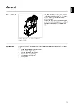
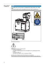
Page 11: ...General 11 ...

Page 12: ...12 ...

Page 13: ...orches All optional equipment required for effect ive welding torch cleaning can be installed directly on the welding torch service sta tion Applications The welding torch service station is used in automated MIG MAG applications in a robot cell In the automotive and supply industry In equipment engineering In chemical plant construction In mechanical engineering In rail vehicle construction In sh...

Page 14: ...a p max 24 V 0 25 A 6 bar 87PSI Warning Notices on the Device WARNING Risk of serious injuries due to moving mechanical parts compressed air parting agent mixture discharged from the parting agent injection nozzles flying debris chips etc compressed air stored at 16 bar in the pressure booster Release stored compressed air before maintenance and servicing During maintenance and servicing keep the ...

Page 15: ...ope of supply Types of parting agent and their use Robacta Reamer parting agent for spraying the welding torch after the cleaning process It is recommended that the welding torch be sprayed with the Robacta Reamer parting agent for all applications Options OPT i Robacta TSS BK Profinet 4 101 127 CK OPT i Robacta TSS BK Profibus 4 101 179 CK OPT i Robacta TSS BK DeviceNet 4 101 180 CK OPT i Robacta...

Page 16: ...amer Twin cleaning unit 44 0450 1282 Robacta Reamer V Easy Single clean ing unit 44 0450 1444 Robacta Reamer V 70 Han12P cleaning unit 44 0450 1961 OPT i TSS Reamer Single 4 001 123 OPT i TSS Reamer V70 4 001 133 Reamer Single 600 mm connection cable 43 0009 6290 depending on the system configuration installation set required for the installation of the respective device Detailed Informa tion on t...

Page 17: ...tion can be transported as follows manually by at least two people on a pallet using a low lift truck on a pallet using a counterbalanced lift truck The welding torch service station can be lifted from the pallet and positioned at the installation site using a crane and two belts When selecting the belt length for this ensure that the welding torch service station will not be damaged when lifting ...

Page 18: ...18 ...

Page 19: ...Operating controls connections and mechanical components 19 ...

Page 20: ...20 ...

Page 21: ...can result in severe personal injury and damage to property The functions described may only be used by trained personnel Do not perform the work described below until you have thoroughly read and under stood the following documents This document All Operating Instructions for system components especially the safety rules Connections and mechanical com ponents 1 2 3 4 5 6 7 8 B A 1 Outer gas nozzl...

Page 22: ...s nozzles 1 1 3 Inner gas nozzle cleaning brush for cleaning the contact tip 4 Collecting tray 5 Flap for parting agent container 6 Manometer 7 Ground connection 8 Installation area for optional equipment 10 9 Std I O View A 9 Robot control unit connection Standard I O 37 pin 10 Pressure regulator Connection devices supply air Operating pressure 5 5 6 bar 22 ...

Page 23: ...connections 11 14 for external optional equipment are equal 15 Compressed air connection Nominal pressure 6 bar 16 Compressed air connection Nominal pressure 6 bar 17 Compressed air connection Nominal pressure 6 bar 18 Compressed air connection Nominal pressure 6 bar 19 Compressed air connection Nominal pressure 6 bar 20 Parting agent connection 21 Compressed air connection Gas purging through hos...

Page 24: ...omatically This can result in severe personal injury and damage to property The device must only be supplied with power using an emergency stop voltage cir cuit Assignment of standard I O con nection for robot control CAUTION Danger from overcurrent Damage to the bearings may result Provide the power supply with 1 5 A fuse protection against overcurrent NOTE To avoid interference keep the line len...

Page 25: ... fill level optional 11 Reserved 12 Reserved O13 RR Single gas nozzle free 14 Reserved I 15 RR Single start cleaning 16 Reserved I 17 Reserved I 18 Reserved O19 Reserved O20 Reserved O21 TC cleaning error I 22 TC spraying O23 TC ready I 24 TC start cleaning O25 TC parting agent low level OK I 26 TC quick stop 27 NC O28 RR Twin gas nozzle free 29 Reserved 30 Reserved I 31 RR Twin start cleaning 32 ...

Page 26: ...10 2436 EtherCAT Robacta TSS i 42 0410 2550 Ethernet IP Robacta TSS i Assignment of external optional equipment con nection CAUTION Danger from overcurrent Damage to the bearings may result Provide the power supply with 1 5 A fuse protection against overcurrent NOTE To avoid interference keep the line length between the welding torch service sta tion and the robot control unit as short as possible...

Page 27: ...14 Reserved O15 RR Single start cleaning 16 Reserved O17 Reserved O18 Reserved I 19 Reserved I 20 Reserved I 21 TC cleaning error O22 TC spraying I 23 TC ready O24 TC start cleaning I 25 TC agent low level OK O26 TC quick stop 27 NC I 28 RR Twin gas nozzle free I 29 Reserved 30 Reserved O31 RR Twin start cleaning I 32 RR motor bottom I 33 RR motor top O34 WC RR cut wire electrode 27 EN US ...

Page 28: ...O35 RR clamp gas nozzle O36 RR lifting device upwards O37 Reserved TC Robacta TC 2000 WC wire cutter RR Robacta Reamer 28 ...

Page 29: ...be installed in a robot interface the number is lim ited by the size of the housing The process data frame changes when additional fieldbus terminals are installed Input signals from welding torch service sta tion to robot No Signal designation Action E01 Pressure switch signal High E02 Parting agent fill level OK optional High E03 Signal Gas OK Single High E04 Signal Gas OK Twin High E05 Reserved...

Page 30: ...o Signal designation Action A01 High end gas purging from the front High A02 High end gas purging through the hosepack High A03 External valve brush cleaning High A04 Internal valve brush cleaning High A05 Inject valve parting agent pump High A06 TC quick stop High A07 Reserved A08 Reserved A09 RR Single start cleaning High A10 TC cleaning start High A11 RR Twin start cleaning High 30 ...

Page 31: ...A12 WC RR cut wire electrode High A13 RR clamp gas nozzle High A14 RR cleaning motor up stroke High A15 Reserved A16 RR TC spraying High RR Robacta Reamer TC Robacta TC WC wire cutter 31 EN US ...

Page 32: ...32 ...

Page 33: ...Installation and Startup 33 ...

Page 34: ...34 ...

Page 35: ... these Operating Instructions all Operating Instructions for system components especially the safety rules WARNING Danger due to machines starting automatically This can result in severe personal injury and damage to property In addition to these Operating Instructions observe the safety rules of the robot manufacturer and welding system manufacturer For your personal safety make sure that all pro...

Page 36: ...d with electricity if there are TC cleaning units keep all ferromagnetic parts e g tools away from the device keep hands hair the face items of property and all items of clothing away from the optional devices wear hearing protection wear protective goggles with side protection WARNING Danger due to insufficient ground conductor connection Serious injury or damage to property can result The housin...

Page 37: ...er falling vertically The device can be operated in accordance with protection class IP21 Direct moisture e g from rain must be avoided NOTE Install the device at a minimum distance of 1 m 40 in away from IT equipment and control lines as well as from the welding process NOTE Install the device with an all round clearance of at least 0 5 m 19 69 in to walls neighboring devices or other objects NOT...

Page 38: ...ion so that it is horizontal Use four screws to anchor the service station to the surface NOTE Depending on the surface different dowels and screws may be required to anchor the service station to the surface Therefore dowels and screws are not part of the scope of supply for the service station The system installer is responsible for selecting the proper dowels and screws 2 2 2 2 3 1 1 Position t...

Page 39: ...optional equip ment overview The installation of the optional equipment available for the welding torch service station is made up of the following sections 1 Installing Touch Sense 2 Installing the wire cutter 3 Installing the cleaning unit Robacta TC 2000 Robacta Reamer Twin 4 Installing the level sensor 5 Inserting the parting agent container 6 Installing the TCP tip 7 Installing the Robacta Re...

Page 40: ...rench 4 mm Allen key Cable ties Diagonal cutting pliers Slotted screwdriver Hammer Installing Touch Sense 2 1 1 2 2 2 2 3 2 6x TX25 1 Knock out the side round opening 2 Remove the 6 TX25 screws 3 Remove the cover 5 4 4 Knock out the top round opening 5 Remove the knocked out material from above 40 ...

Page 41: ... a 3 mm Allen screw 9 Insert the cable into the knocked out opening 10 10 2x TX20 NOTE When installing the Touch Sense do not pinch kink shear off or otherwise damage the cable 10 Install the Touch Sense on the service station with 2 TX20 screws The Touch Sense can be installed in all 90 positions 1 4 1 8 2 2 2 6 1 4 1 8 2 2 2 6 1 4 1 8 2 2 2 6 1 4 1 8 2 2 2 6 41 EN US ...

Page 42: ...lastic insert to the housing wall size 17 mm 1 2 3 15 14 13 Arrange serrated washer and cable lug on the Allen screw according to the diagram cable lug 1 serrated washer 2 screw 3 14 Screw the Allen screw into the plastic insert size 4 mm and then tighten 16 16 15 Fix the cable in place using 2 cable ties 16 Trim cable ties 42 ...

Page 43: ...9 Apply cable lug of an additional cable to the screw protruding out of the housing and use the serrated washer and 8 mm hexagonal nut from the scope of supply to secure the OPT i TSS TCP Touch Sense 20 Use the additional cable to establish a connection to the workpiece ground 43 EN US ...

Page 44: ...r to the welding torch service station OPT i TSS Wire Cutter installation set for wire cutter 4 001 098 CK Installing the Wire Cutter 1 2 1 Knock out the opening 2 Remove the knocked out material from above 3 3 4 3 3 4 4 3 3 Install the wire cutter on the wire cutter installation set 3 using two 5 mm Allen screws and two 10 mm hexagonal nuts 4 using one 5 mm Allen screw and one 10 mm hexagonal nut...

Page 45: ...ition the wire cutter according to the diagram 7 Use four 6 mm Allen screws and four washers to install the wire cutter on the service station 8 10 9 8 Connect the control cable 9 Connect the compressed air hose 10 Apply the cover Operating Instructions The wire cutter can be used to cut two wire electrodes with a diameter of up to 1 6 mm 0 063 in With the 0 welding torch the wire electrodes must ...

Page 46: ...crewdriver Hammer Additionally Required The following accessories are required for installing a Robacta TC 2000 cleaning unit on the welding torch service station OPT i TSS TC2000 installation set for Robacta TC 2000 4 001 012 CK Installing the Robacta TC 2000 Cleaning Unit 1 1 1 Knock out the round opening 2 3 3 3 3 2 Position the mounting plate 3 Use four 6 mm Allen screws and four washers to in...

Page 47: ... ensure that the mains cable and control cable remain in the middle of the recess 6 Apply Robacta TC 2000 cleaning unit to the mounting plate 7 Use four TX25 screws to secure Robacta TC 2000 cleaning unit to the mounting plate 8 Connect control cable to the TC 2000 cleaning unit 9 11 10 1 0 11 9 Attach control cable to the service sta tion 10 Connect hose for parting agent to the service station a...

Page 48: ...ired The following accessories are required for installing a Robacta Reamer Twin cleaning unit on the welding torch service station OPT i TSS Reamer Twin 4 001 109 Removing the Injection Device and Existing Clamping System 2 1 1 1 1 1 1 Loosen 5 Allen screws size 3 mm 2 Remove the housing casing 5 4 3 7 6 3 Disconnect the hose 4 Push the hose inside the device 5 Disconnect the hose 6 Loosen and re...

Page 49: ...lace using a cable tie 10 Insert the rubber bushing into the free opening 11 12 11 11 Loosen 2 Allen screws size 5 mm 12 Remove the 3 piece clamping device element 13 14 13 Remove countersunk Allen screw size 5 mm 14 Remove the clamping device element 49 EN US ...

Page 50: ...ice element with M8 x 25 mm countersunk Allen screw size 5 mm 2 2 2 Insert two 3 x 12 mm dowel pins 3 3 4 4 3 Connect the clamping device ele ments together 4 Screw the clamping device elements together with two washers and two M6 x 25 mm Allen screws size 5 mm 50 ...

Page 51: ... M6 x 16 mm Allen screws size 5 mm 0 5 mm 6 Make sure that there is a distance of approx 0 5 mm between the clamping device elements 8 7 8 8 8 8 7 Position the housing casing 8 Install the housing casing with five M4 x 8 mm Allen screws size 3 mm 51 EN US ...

Page 52: ...r vice station as shown 1 1 Depending on the intended mounting position knock out the corresponding rectangular opening 2 3 3 3 3 3 3 2 Position the Robacta Reamer Twin cleaning unit on the service station Possible mounting positions 3 Secure the Robacta Reamer Twin cleaning unit with 6 washers and 6 Allen screws size 6 mm 52 ...

Page 53: ...4 5 4 5 4 Connect the Robacta Reamer control cable 5 Connect the hose for the compressed air supply 53 EN US ...

Page 54: ...spring pins of the collecting tray to the left and right and swing col lecting tray out 2 Remove three TX25 screws on the left 3 Remove three TX25 screws on the right 4 5 4 4 Remove frame 5 Open flap for parting agent container 6 7 7 6 Apply level sensor to the threaded pin on the flap 7 Use two 5 mm hexagonal nuts to secure the level sensor 54 ...

Page 55: ...the recess 11 Insert the frame 12 Lift up the frame 13 14 14 14 13 13 15 13 13 13 14 14 14 13 Use three TX25 screws to secure the frame on the right 14 Use three TX25 screws to secure the frame on the left 15 Pull spring pins and insert collecting tray Carry out the commissioning of the level sensor in accordance with the Commissioning level sensor instructions 42 0410 2553 The instructions are in...

Page 56: ... hose out of the flap 3 Insert parting agent container until it reaches the stop 4 Open the parting agent container 7 5 6 6 5 Insert the hose into the parting agent container 6 Secure the cap of the hose NOTE When closing the flap ensure that the hose is not pinched kinked cut or oth erwise damaged 7 Close flap for parting agent container 56 ...

Page 57: ... TCP Tool Center Point Instead of the Touch Sense a TCP tip can also be fitted This can be done without knocking out the round holes on the side and top 2 2 x TX20 1 1 1 Use 2 TX20 screws to install the TCP tip on the service station 2 Unscrew the protective cap for opera tion 57 EN US ...

Page 58: ...12P are both always active Which of the two cleaning units is started up depends on the robot program Tools required 6 mm Allen key 10 mm wrench 19 mm wrench Additionally required The following accessories are required for installing a Robacta Reamer V Easy cleaning unit on the welding torch service station OPT i TSS Reamer Single 4 001 123 The following accessories are required for installing a R...

Page 59: ...r the 4 holes 2 3 3 3 3 2 Place the Robacta Reamer V Easy on the intermediate plate 3 Use four 6 mm Allen screws and four washers to install the Robacta Reamer V Easy on the service station 4 5 4 4 6 4 Remove three 10 mm hexagonal bolts 5 Remove the cover 6 Knock out the rectangular opening 59 EN US ...

Page 60: ... the Robacta Reamer V Easy with three 10 mm hexagonal bolts 9 Secure the new cover to the service station with two 6 mm Allen screws 1 0 10 Install spool valve Size 19 mm 1 1 11 11 Connect the control cable to the ser vice station and Robacta Reamer V Easy 60 ...

Page 61: ...12 12 12 Connect the compressed air supply 61 EN US ...

Page 62: ...ollows 4 3 2 1 3 3 2 2 1 Remove collecting tray 2 Remove three TX25 screws on the left 3 Remove three TX25 screws on the right 4 Remove frame Position of the bus coupler Requirements for Starting Up The following requirements must be met in order to commission the cleaning device Securely bolt the welding torch service station to the surface Any available optional equipment installed on the weldin...

Page 63: ...st pressure on the manometer 5 5 6 bar 6 Check that all equipment parts and covers are correctly installed IMPORTANT Before welding for the first time a complete cleaning process must be car ried out 63 EN US ...

Page 64: ...64 ...

Page 65: ...Cleaning Program Sequence 65 ...

Page 66: ...66 ...

Page 67: ...e cutter Robacta TC 2000 cleaning unit and dipping bowl For other configurations refer to the Operating Instructions of the components Welding Pos A Wire cutter retract wire Pos B Robacta TC 2000 dipping bowl Pos C Robacta TC 2000 Pos D High pressure gas purging with parting agent 1st contact tip Pos E Outer gas nozzle cleaning brush 2x Pos F Inner gas nozzle cleaning brush 1st and 2nd contact tip...

Page 68: ...A B C D E F G 68 ...

Page 69: ...h a maximum of 75 mm 2 95 in into the dipping bowl The gas holes 1 must remain dry Robacta TC 2000 Robacta TC 2000 is an electromagnetic cleaning unit for welding torch cleaning in steel applications After 50 seconds of charging time the maximum magnetic flux density is available for the cleaning process The cleaning process discharge process is initiated by the Cleaning start signal Specification...

Page 70: ... A 50 mm 1 97 in Set Start wirefeeding signal on the power source Wait approx 0 5 seconds Reset Start wirefeeding signal on the power source Move in with the wire electrode in the wire cutter blade Speed 50 cm min 19 69 ipm Set external signal Cut wire electrode Wait 0 5 seconds Move straight up approx 50 mm 1 97 in above wire cut ter blades Speed 50 cm min 19 69 ipm 70 ...

Page 71: ...Reset external signal Cut wire electrode Set Retract wire electrode signal on the power source Wait approx 2 3 seconds Reset Retract wire electrode signal on the power source 71 EN US ...

Page 72: ... in 75 mm 2 95 in Max insertion depth Move into dipping bowl max speed 50 cm min 19 69 ipm max insertion depth 75 mm 2 95 in Wait 2 3 seconds Move to position B approx 200 mm 7 9 in centrally above dipping bowl max speed 50 cm min 19 69 ipm Set gas purging through welding torch option Wait 0 5 seconds Reset gas purging through welding torch option 72 ...

Page 73: ...or coil shapes other than Twin as per Robacta TC 2000 Operating Instructions Move into TC 2000 max speed 50 cm min 19 69 ipm Insertion depth 54 mm 2 13 in Set external signal Start cleaning Wait 0 5 seconds Reset external signal Start cleaning Move to position C approx 50 mm 1 97 in centrally above cleaning coil max speed 50 cm min 19 69 ipm 73 EN US ...

Page 74: ...7 in Set external signal Pump for parting agent Wait 0 2 0 3 seconds specification of the parting agent volume via the dur ation Reset external signal Pump for parting agent Move into the high pressure gas pur ging max speed 50 cm min 19 69 ipm Select insertion depth so that the dis tance between contact tip and nozzle is 3 mm 0 12 in Set external signal External valve brush cleaning Set external ...

Page 75: ...Reset external signal High end gas purging from front Wait 1 second Reset external signal External valve brush cleaning 75 EN US ...

Page 76: ...rnal gas nozzle cleaning brush max speed 50 cm min 19 69 ipm max insertion depth 12 mm 0 47 in Pass through the external gas nozzle cleaning brush x2 forwards and backwards max speed 50 cm min 19 69 ipm max insertion depth 12 mm 0 47 in Turn welding torch 180 Alternative Break the second cleaning brush free and pass through each cleaning brush x 1 Pass through the external gas nozzle cleaning brus...

Page 77: ...Move to position E approx 50 mm 1 97 in centrally above the outer gas nozzle cleaning brush and approx 20 mm 0 79 in in front of the housing of the service station max speed 50 cm min 19 69 ipm 77 EN US ...

Page 78: ... 69 ipm max insertion depth 1 3 of the brush length Wait 2 3 seconds Move to position F2 approx 50 mm 1 97 in centrally above the inner gas nozzle cleaning brush Contact tip 2 vertical to the service sta tion max speed 50 cm min 19 69 ipm Move into the inner gas nozzle clean ing brush max speed 50 cm min 19 69 ipm max insertion depth 1 3 of the brush length Wait 2 3 seconds Move to position F appr...

Page 79: ...Reset external signal Internal valve brush cleaning 79 EN US ...

Page 80: ...onds specification of the parting agent volume via the duration Reset external signal Pump for parting agent Move into the high pressure gas pur ging max speed 50 cm min 19 69 ipm Select insertion depth so that the dis tance between contact tip 2 and nozzle is 3 mm 0 12 in Set external signal High end gas purging from front Set external signal External valve brush cleaning Wait 0 5 1 5 seconds Res...

Page 81: ...al signal External valve brush cleaning Move to position D2 approx 50 mm 1 97 in centrally above the opening for the high pressure gas purging Contact tip 2 vertical to the service sta tion max speed 50 cm min 19 69 ipm 81 EN US ...

Page 82: ... of the wire electrodes depending on application Speed High speed mode G x mm x in Set Wirefeeding on signal on the power source Wait until the wire electrode touches the Touch Sense option the wirefeeding is automatically stopped Reset Wirefeeding on signal on the power source End of the cleaning process Welding 82 ...

Page 83: ...or approx 2 5 4 5 seconds approx 20 longer than retracting the wire Wait 2 5 4 5 seconds Reset Start wirefeeding signal on the power source Move into wire cutter insertion depth x mm above the cut ting tool x stick out of the wire electrodes depending on application max speed 50 cm min 19 69 ipm Set external signal Cut wire electrode Wait 0 5 seconds Move straight up approx 50 mm 1 97 in centrally...

Page 84: ...Reset external signal Cut wire electrode End of the cleaning process Welding 84 ...

Page 85: ...Troubleshooting Maintenance and Disposal 85 ...

Page 86: ...86 ...

Page 87: ... these Operating Instructions all Operating Instructions for system components especially the safety rules WARNING Danger due to machines starting automatically This can result in severe personal injury and damage to property In addition to these Operating Instructions observe the safety rules of the robot manufacturer and welding system manufacturer For your personal safety make sure that all pro...

Page 88: ...d with electricity if there are TC cleaning units keep all ferromagnetic parts e g tools away from the device keep hands hair the face items of property and all items of clothing away from the optional devices wear hearing protection wear protective goggles with side protection WARNING Danger due to insufficient ground conductor connection Serious injury or damage to property can result The housin...

Page 89: ...too low Set injection quantity injection time Intake filter in Robacta Reamer parting agent container dirty Blow out the intake filter in the Robacta Reamer parting agent container from the inside out with compressed air using the intake hose 2 3 4 1 Parting agent hose kinked Remove kink if necessary replace hose Parting agent pump faulty Contact After Sales Service No signal at the parting agent ...

Page 90: ...line and replace if necessary Pressure regulator not set correctly Check pressure at pressure regulator set pressure to 5 5 6 bar Pressure booster faulty Contact After Sales Service Inlet pressure at the pressure booster too low Check inlet pressure Valve faulty Contact After Sales Service Nozzle blocked Clean nozzle replace if necessary Cause Remedy Cause Remedy Cause Remedy Cause Remedy Cause Re...

Page 91: ...r supply and release stored compressed air before maintenance and servicing During maintenance and servicing keep the device de energized and depressur ized Release pressure 2 1 1 Disconnect compressed air supply 2 Open valve Fully release pressure Before Every Start up Check the fill level in the parting agent container and top up if necessary Check cleaning brushes for contamination and wear rep...

Page 92: ...the dirt deflector under the round brushes and clean with compressed air Every 6 Months CAUTION Risk of damage to electronic parts Do not blow electronic parts clean from a short distance away 1 Open the welding torch service station and blow clean with dry and reduced com pressed air Every 12 Months 1 Have a Fronius service technician perform a safety inspection on the cleaning device Disposal Ma...

Page 93: ...s injuries may result Switch off the compressed air supply and release stored compressed air before maintenance and servicing During maintenance and servicing keep the device de energized and depressur ized Release pressure 2 1 1 Disconnect compressed air supply 2 Open valve Fully release pressure Replacing the Outer Gas Nozzle Cleaning Brushes 2 1 1 1 Loosen knurled screws 2 Remove cover 93 EN US...

Page 94: ...olt 6 Remove hexagonal bolt and fixing washer 7 Remove right hand cleaning brush 8 Repeat steps 4 7 for the left hand cleaning brush NOTE Always replace both cleaning brushes The assembly of the cleaning brushes is carried out in reverse order Replacing the inner gas nozzle cleaning brush 2 1 1 1 Loosen knurled screws 2 Remove cover 94 ...

Page 95: ...PORTANT During installation press and hold the locking button and insert the cleaning brush until it engages Changing the nozzle for the high pressure gas purging 2 1 1 1 Loosen knurled screws 2 Remove cover 3 4 3 Pull out spring bolt 4 Remove the nozzle from above 95 EN US ...

Page 96: ...ctly secured nozzle can be thrown out of the device when compressed air is supplied and cause a variety of injuries The sequence of the following steps must be observed Always insert the nozzle as far as it will go Check that the nozzle is correctly secured 1 Pull out and hold the spring bolt 2 Insert the nozzle as far as it will go 3 Release the spring bolt and make sure it engages 4 Fit cover 96...

Page 97: ...Appendix 97 ...

Page 98: ...98 ...

Page 99: ... Instructions for the optional equipment Robacta TSS i Supply voltage 24 V DC Nominal output 24 W Compressed air supply 6 bar 86 99 psi Minimum cleaning interval From 20 s Degree of protection IP 21 Dimensions l w h 765 405 1000 mm 30 1 15 9 39 4 in Weight without optional equipment incl 10 l parting agent canister 82 kg 180 78 Ib EMC device class A Mark of conformity CE 99 EN US ...

Page 100: ...S INTERNATIONAL GMBH Froniusstraße 1 A 4643 Pettenbach AUSTRIA contact fronius com www fronius com Under www fronius com contact you will find the addresses of all Fronius Sales Service Partners and locations ...

Reviews: