background image

/ Perfect Charging / 

Perfect Welding

 / Solar Energy

42,0426,0006,EN 005-18032019

VR 1500
VR 1500 PSA
VR 1500 - 11
VR 1500 - 12
VR 1500 - 30
VR 1550
VR 1550 CMT-WS

Operating Instructions
Spare parts list

Wire-feed unit

EN

Summary of Contents for VR 1500-11

Page 1: ...fect Charging Perfect Welding Solar Energy 42 0426 0006 EN 005 18032019 VR 1500 VR 1500 PSA VR 1500 11 VR 1500 12 VR 1500 30 VR 1550 VR 1550 CMT WS Operating Instructions Spare parts list Wire feed unit EN ...

Page 2: ...2 ...

Page 3: ... essential prerequisites for excellent results Explanation of safety symbols DANGER Indicates immediate and real danger If it is not avoided death or serious injury will result WARNING Indicates a potentially dangerous situation Death or serious injury may result if appropriate precautions are not taken CAUTION Indicates a situation where damage or injury could occur If it is not avoided minor inj...

Page 4: ...4 ...

Page 5: ...ing notices on the device 18 Options 19 General remarks 19 Unreeling wirefeeders 19 Optional installation and conversion kits 20 Expansions and versions 20 Controls connections and mechanical components 22 General remarks 22 Front of wirefeeder 22 Rear of wire feed unit 23 Notes regarding the operation of the VR 1500 11 and VR 1500 12 25 Cooling the wirefeeder motor 25 Welding current above 500 A ...

Page 6: ...ire end special function 35 Troubleshooting 35 Error reset 35 Care maintenance and disposal 36 General remarks 36 Every start up 36 Every 6 months 36 Disposal 36 Technical data 37 General remarks 37 VR 1500 37 VR 1500 11 37 VR 1500 12 38 VR 1500 30 38 VR 1550 CMT WS 39 Appendix 41 Spare parts list VR 1500 VR 1550 42 Circuit diagrams VR 1500 VR 1500 PSA VR 1550 53 ...

Page 7: ...d General in the operating instructions for the device Before switching on the device rectify any faults that could compromise safety This is for your personal safety Proper use The device is to be used exclusively for its intended purpose The device is intended solely for the welding processes specified on the rating plate Any use above and beyond this purpose is deemed improper The manufacturer ...

Page 8: ...manner Obligations of personnel Before using the device all persons instructed to do so undertake to observe the basic instructions regarding safety at work and accident prevention to read these operating instructions especially the Safety rules section and sign to confirm that they have understood them and will follow them Before leaving the workplace ensure that people or property cannot come to...

Page 9: ...ry Keep all persons especially children out of the working area while any devices are in op eration or welding is in progress If however there are people in the vicinity Make them aware of all the dangers risk of dazzling by the arc injury from flying sparks harmful welding fumes noise possible risks from mains current and welding current etc Provide suitable protective equipment Alternatively ere...

Page 10: ...rs and all pieces of metal that are in contact with the welding wire are live Always set the wirefeeder up on a sufficiently insulated surface or use a suitable insulated wirefeeder holder Make sure that you and others are protected with an adequately insulated dry temporary backing or cover for the earth or ground potential This temporary backing or cover must extend over the entire area between ...

Page 11: ...ch the workpiece clamp as close as possible to the area that is to be welded If the floor is electrically conductive the device must be set up with sufficient insulating ma terial to insulate it from the floor If distribution boards twin head mounts etc are being used note the following The elec trode of the welding torch electrode holder that is not used is also live Make sure that the welding to...

Page 12: ...ation EMF measures Electromagnetic fields may pose as yet unknown risks to health effects on the health of others in the vicinity e g wearers of pacemakers and hearing aids wearers of pacemakers must seek advice from their doctor before approaching the de vice or any welding that is in progress for safety reasons keep distances between the welding cables and the welder s head torso as large as pos...

Page 13: ... the wire feed unit is attached to a crane holder during welding always use a suitable insulated wirefeeder hoisting attachment MIG MAG and TIG devices If the device has a carrying strap or handle this is intended solely for carrying by hand The carrying strap is not to be used if transporting with a crane counterbalanced lift truck or other mechanical hoist All lifting accessories straps handles ...

Page 14: ...ourless and odourless and in the event of a leak can displace the ox ygen in the ambient air Ensure an adequate supply of fresh air with a ventilation rate of at least 20 m hour Observe safety and maintenance instructions on the shielding gas cylinder or the main gas supply Close the shielding gas cylinder valve or main gas supply if no welding is taking place Check the shielding gas cylinder or m...

Page 15: ...mability etc Only use suitable original coolant from the manufacturer Do not mix the manufacturer s original coolant with other coolants Only connect the manufacturer s system components to the cooling circuit The manufacturer accepts no liability for damage resulting from use of other system com ponents or a different coolant In addition all warranty claims will be forfeited Cooling Liquid FCL 10...

Page 16: ...ty Any device that you no longer require must either be returned to your dealer or given to one of the approved collection and recycling facilities in your area Ignoring this European Directive may have potentially adverse af fects on the environment and your health Safety symbols Devices with the CE mark satisfy the essential requirements of the low voltage and elec tromagnetic compatibility dire...

Page 17: ... however must be earthed grounded separately Application area The robot wirefeeder is specially designed for fitting to the robot arm and can be used in conjunction with the TS 4000 5000 TPS 3200 4000 5000 power sources The robot wirefeeder is suitable for all standard shielding gases The VR 1500 11 and VR 1500 12 are also used for flux core wire applications The VR 1500 12 is primarily used for c...

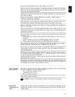
Page 18: ... damage Do not use the functions described here until you have fully read and understood the following documents These operating instructions all the operating instructions for the system components especially the safety rules Welding is dangerous The following basic requirements must be met welders must be sufficiently qualified use appropriate protective equipment all persons not involved in the...

Page 19: ...efeeders are available in the following versions VR 1500 cover for protecting the drive components of the robot wirefeeder VR 1500 adapter plate for fitting the robot wirefeeder to the robot arm or fitting the hosepack strain relief device VR 1500 torch support to stabilise and support the torch hosepack increased service life for the torch hosepack Wirefeeding hose for protecting the wire along i...

Page 20: ...or subsequent installation of the digital gas control Gas economiser valve installation kit for subsequent installation of a gas economiser valve Fixable tensioning lever installation kit for plastic motor plate for subsequent installation of a fixable tensioning lever so that contact pressure cannot be accidentally adjusted Wire end connector installation kit for subsequent installation of the op...

Page 21: ...the control unit and motor plate are used separately The control unit must be earthed The motor plate must be insulated 3 roller wire straightening section Tuchel plug VR 1500 wire end sensor incl spool cover VR 1500 wire end sensor for welding wire drum without control cable ...

Page 22: ...r threading the wire electrode into the torch hosepack with no flow of gas or cur rent 5 Additional fan 6 Robacta robot welding torch connection on VR 1500 see circuit diagram X10 for pin assignment or Wire buffer connection on VR 1550 CMT WS and VR 1550 CMT installation kit optional 7 Robacta robot welding torch connection on VR 1550 CMT WS see circuit diagram X10 for pin assignment 8 Blanking co...

Page 23: ...f the VR 1550 CMT installation kit is plugged into 2 and the LocalNet connection is plugged into 14 3 current connection with bayonet latch interconnecting hosepack 4 2nd socket with bayonet latch optional 900 A installation kit 5 Blanking cover wire end connector optional 6 Blanking cover 7 Wire infeed tube 8 VR 1500 cover optional 9 Shielding gas connection 10 Water return connection red interco...

Page 24: ...24 15 Blanking cover AIR IN torch blow out connection high end option max 15 bar 16 Additional filter ...

Page 25: ...00 A only operate the VR 1500 11 VR 1500 12 and VR 1500 30 wirefeeders with adequately dimensioned Fronius welding torches that have an F connection PMR 4000 push pull option NOTE If the PMR 4000 push pull option is installed on the VR 1500 11 and VR 1500 30 wirefeeders the power source must be equipped with an increased power supply 55 V DC 8 A Applications with unreeling wire feeders NOTE If unr...

Page 26: ...ower source must be equipped with an increased power supply 55 V DC 8 A Operating the VR 1500 12 with an unreeling wire feeder NOTE To operate the VR 1500 12 with an unreeling wirefeeder the VR 1500 12 must be equipped with an increased motor supply installation kit ...

Page 27: ...ns switch to the O position Fix the strain relief device of the interconnecting hosepack to the VR 1500 hosepack holder Connect the gas hose of the interconnecting hosepack to the shielding gas connection 9 Tighten the union nut on the gas hose If available connect the water flow and water return hoses of the interconnecting hosepack to the water flow 11 and water return 10 connections ensuring th...

Page 28: ... wirefeeder VR 1500 11 12 30 Connecting the interconnecting hosepack to the wirefeeder A Interconnecting hosepack wirefeeder end R red B blue A Interconnecting hosepack wirefeeder end C 2nd power cable optional R red B blue 10 11 9 1 3 B R A 10 11 9 4 3 B R 1 A C ...

Page 29: ...s correc tly set up Insert it infeed tube first into the torch connection 1 and tigh ten the union nut by hand to secure the torch in place Plug the control plug of the welding torch into the Robacta robot welding torch connection 3 and tighten the union nut to secure in place If present connect the external water flow 4 and return 5 connections cor rectly matching the colours If present connect t...

Page 30: ...onnection 1 Fixing welding torch in place using a knurled screw Fix the welding torch in place using a knurled screw 2 Connecting water connections for water flow and wa ter return If present plug the control plug of the welding torch into the Robacta robot welding torch connection 3 and tigh ten the union nut to secure it in place If present connect the external water flow 4 and return 5 connecti...

Page 31: ...ly use feed rollers that match the wire electrode An overview of the feed rollers available and their possible areas of use can be found in the spare parts lists USA wirefeeders In the USA all wirefeeders are delivered without feed rollers After inserting the wirespool the feed rollers must be inserted into the wirefeeder inserting replac ing feed rollers 1 2 3 4 4 5 2 1 6 6 1 4 5 3 2 1 2 1 2 3 1 ...

Page 32: ...e wire electrode and the earthed enclosure of a robot cell chafed wirefeeding hoses exposing the wire electrode Using wirefeeding hoses ensures that the wire electrode remains insulated as it is trans ported towards the wirefeeder To prevent chafing do not route the wirefeeding hoses over sharp edges Use hose holders or hose protectors as necessary Coupling pieces and hoods for welding wire drums ...

Page 33: ...eading button or the torch trigger keep the welding torch away from your face and body and wear suitable protective goggles 1 2 Set the contact pressure NOTE Set the contact pressure in such a way that the wire electrode is not deformed but nevertheless ensures proper wirefeeding 2 2 3 3 1 3 4 5 6 ...

Page 34: ...34 1 Contact pressure standard values SC TR PL Aluminium 1 5 3 5 4 5 Steel 3 4 1 5 CrNi 3 4 1 5 Feed rollers SC Semi cylindrical rollers TR Trapeze rollers PL Plastic rollers 1 1 1 ...

Page 35: ...d thread in the welding wire acknowledge the error on the power source Cause Additional fan filter is contaminated air supply for the additional fan is no longer sufficient to cool the power electronics the power electronics temper ature switch has tripped Remedy Clean filter or replace acknowledge the error on the power source Cause Ambient temperature too high Remedy Reduce ambient temperature i...

Page 36: ...sing a suitable measuring instrument check to make sure that electrically charged components e g capacitors have been discharged Every start up Check welding torch interconnecting hosepack and ground earth connection for signs of damage Perform a visual check on the feed rollers and inner liners for signs of damage Check contact pressure of feed rollers and adjust if necessary Check brake and adju...

Page 37: ... in Weight 7 kg 15 43 Ib Drive 4 roller drive Maximum shielding gas pressure 7 bar 101 psi Coolant Original Fronius coolant Maximum coolant pressure 6 bar 87 psi Supply voltage 55 V DC Nominal current 4 A Wire diameter 0 8 3 2 mm 0 03 0 13 in Wire feed speed 0 5 11 m min 19 69 433 07 ipm Torque 11 Nm Degree of protection IP 21 Dimensions l x w x h 400 x 300 x 205 mm 15 75 x 11 81 x 8 07 in Weight ...

Page 38: ...nal fan for the power electronics Maximum shielding gas pressure 7 bar 101 psi Coolant Original Fronius coolant Maximum coolant pressure 6 bar 87 psi Supply voltage 55 V DC Nominal current 4 A Wire diameter 0 8 1 6 mm 0 03 0 06 in Wire feed speed 0 5 30 m min 19 69 1181 10 ipm Torque 3 7 Nm Degree of protection IP 21 Dimensions l x w x h 400 x 300 x 205 mm 15 75 x 11 81 x 8 07 in Weight 8 kg 17 64...

Page 39: ...ire feed speed 0 5 22 m min 19 69 866 14 ipm Torque 4 Nm Degree of protection IP 21 Dimensions l x w x h 405 x 208 x 205 mm 15 75 x 8 19 x 8 07 in Weight 7 kg 15 43 Ib Drive 4 roller drive Maximum shielding gas pressure 7 bar 101 psi Coolant Original Fronius coolant Maximum coolant pressure 6 bar 87 psi ...

Page 40: ...40 ...

Page 41: ...Appendix ...

Page 42: ...42 Spare parts list VR 1500 VR 1550 ...

Page 43: ...43 ...

Page 44: ...44 ...

Page 45: ...45 ...

Page 46: ...46 ...

Page 47: ...47 ...

Page 48: ...48 ...

Page 49: ...048 42 0407 0048 44 0450 0281 G 1 4 42 0001 0942 42 0001 0943 42 0402 0053 42 0405 0239 42 0405 0239 42 0407 0063 42 0407 0063 42 0001 3543 5 8 18UNF W 4m 95mm 4 047 291 W 8m 95mm 4 047 292 W 8m 95mm 4 047 292 800 W 10m 95mm 4 047 396 gewünschte Länge angeben Specify the length required Indiquer la longueur désirée Indicar la longitud deseada Indicare la lunghezza desiderat indicar o comprimento d...

Page 50: ...43 0003 0251 42 0407 0063 42 0407 0442 40 0003 0447 40 0003 0015 44 0001 0971 42 0407 0063 43 0003 0253 42 0407 0048 43 0003 0252 43 0003 0253 42 0407 0048 43 0003 0385 43 0003 0301 40 0001 0012 44 0450 0281 specify length specify length G 1 4 specify length specify length specify length G 1 4 Verb Schlauchpaket W 25M 95mm Verb Schlauchpaket W 30M 95mm 4 047 326 4 047 321 ...

Page 51: ...G 70mm 8m 4 047 412 40 0003 0014 50mm 40 0003 0021 70mm 43 0003 0301 70mm 43 0003 0064 70mm 42 0407 0063 40 0001 0012 32 0405 0226 40 0001 0095 32 0405 0226 42 0407 0482 42 0407 0482 42 0405 0239 42 0405 0239 gewünschte Länge angeben Specify the length required Indiquer la longueur désirée Indicar la longitud deseada Indicare la lunghezza desiderat indicar o comprimento desejado Connection hose pa...

Page 52: ...0 0001 0095 32 0405 0226 42 0407 0482 42 0407 0482 42 0405 0239 42 0405 0239 32 0405 0232 32 0405 0231 32 0405 0180 42 0407 0048 42 0407 0048 40 0003 0078 43 0003 0486 43 0003 0485 32 0405 0180 gewünschte Länge angeben Specify the length required Indiquer la longueur désirée Indicar la longitud deseada Indicare la lunghezza desiderat indicar o comprimento desejado uved te požadovanou délku Connect...

Page 53: ...53 Circuit diagrams VR 1500 VR 1500 PSA VR 1550 VR 1500 ...

Page 54: ...54 VR 1500 PSA ...

Page 55: ...55 VR 1550 VR 1550 CMT WS ...

Page 56: ...RNATIONAL GMBH Vorchdorfer Straße 40 A 4643 Pettenbach Austria E Mail sales fronius com www fronius com Under www fronius com contact you will find the addresses of all Fronius Sales Service Partners and locations ...

Reviews: